Step 1: Create a New Project |

|

|
|
Step 1: Create a New Project |
|
|
Step 1: Create a New Project |
|
|
|
Step 1: Create a New Project |
|
|
Projects hold all the information needed to generate the TestBencher Pro transaction-level model (TLM) including the transaction diagrams, top-level file, and the code generation settings. Chapter 9: TestBencher Advanced Project Features describes projects, sub-projects and creating instances of projects. Here are the steps for creating a basic single-level project.
Create a project:
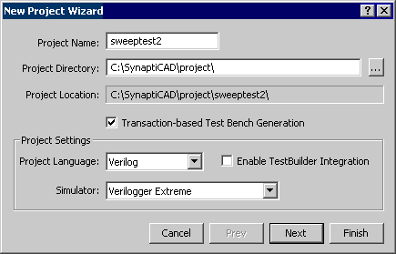
•Select the Project > New Project menu option. This will open the New Project Wizard dialog. •The Project Name will be both the name of the project and the directory where the project is stored. |
|
•Check the Transaction-based Test Bench Generation to make TestBencher generate transaction-level models instead of single diagram test benches. •The Language drop down list defines the generated language for the test bench model. Certain features, such as valid signal types, are dependent on the generated language so this option affects the operation of TestBencher. •If you are using Verilog and want to enable constrained random number generation, check the Enable TestBuilder Integration checkbox. •Press the Next button to move to the next page of the dialog. |
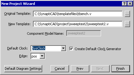
•If your project is clocked, then type in the name of the clocking signal, so that the project will generate a special transactor for the clock. •Press the Default Diagram Settings button to edit the default diagram settings for new diagrams. |
|
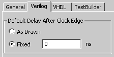
•By default, the Default Delay After Clock Edge setting is fixed to a delay time of 0 for your design. See Section 9.8: Diagram Setting Dialog (TestBencher Only) for information about how this setting is used. |
|
•Press the Finish button to close the New Project Wizard and create the new project. |
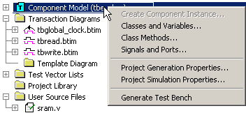
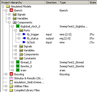
Notice that TestBencher automatically opens the Project window and populates it with the top-level template fileand the template diagram. The template diagram is the starting point for any new transactions that you add to the project. The Project window will be your main resource for navigating through the different parts of the transaction-level model.
Basic controls of the Project window:
•Right click on any node in the Project tree to open a context sensitive pop-up menu that contains all of the operations that can be done to that particular node type. |
|
•Double-left-click on any node to perform the default action for that node (usually open that file or object in an appropriate editor). •To expand or hide branches of a tree, click •Drag and drop the column headings to resize columns. |
Basic Folders of the Project window:
Several folders are created in each project and are used to organize files and objects at the different levels of the test bench. Each of these folders will be discussed at different points in the manual. As an overview:
•Simulated Models folder contains the complete compiled design, the Stimulus & Results diagram, and the log file from the simulator. See Chapter 8: Generation and Simulation for more information. This area is used for analyzing and debugging a compiled simulation. |
|
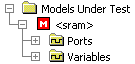
•Models Under Test contains the models with the ports that will hook up to the test bench. By default, the first model that is not instantiated within another model is selected as the model under test when the Extract MUT Ports button is pressed. After the first build, you can optionally right click on other modules and choose Set as Model Under Test to control which models are instantiated in the test bench. See Step 3: Extract Ports into Template Diagram for more information. |
|
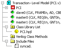
•Transaction-Level Model is the top-level template file for the test bench. The folder contains all of the project-level classes, variables, class methods, and instances of sub-projects. See Chapter 7: Transaction-Level Model Transaction Sequencer for more information. |
|
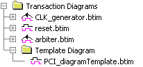
•Transaction Diagrams folder contains the template timing diagram, the timing diagrams that have been added to the project, and the associated generated source code files (in the level beneath the timing diagram). Master diagrams are shown with the waveform icon, and Slave diagrams are shown with the loop back icon. See Chapter 2: Timing Transactor Basics for more information. |
|
•Test Vector Files folder contains input and output test vector files. Chapter 8: Classes and Variables for more information. |
|
•Project Library folder holds any sub-projects that may be instantiated within the current project. Section 9.1: Sub-Projects discusses this folder. |
|
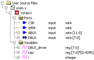
•User Source Files folder contains source files for use in the test bench. Files with a green check-mark icon have been compiled into the test bench; files with a red X icon have not yet been compiled Step 3: Extract MUT Ports into Template Diagram has more information. |
|