9.8 Diagram Settings dialog (TestBencher only) |

|

|
|
9.8 Diagram Settings dialog (TestBencher only) |
|
|
9.8 Diagram Settings dialog (TestBencher only) |
|
|
|
9.8 Diagram Settings dialog (TestBencher only) |
|
|
In TestBencher Pro, the Diagram Settings dialog sets diagram properties that are saved in the HPJ project file. These only affect a specific diagram, but since the settings are stored in the project, they can be different across different projects. These settings control how the source code is generated for a timing diagram and provide defaults for new items added to a timing diagram. In particular, this dialog lets you enable verbose code generation options for each timing diagram, which is especially useful for debugging a transaction. The settings for the default diagram and for each timing diagram in the project are saved separately. Since this dialog controls code generation options that are specific to TestBencher it is not available for BugHunter-style projects or for Reactive Test Bench Generation. Properties that affect the basic operation of the timing diagram and are saved in the BTIM file, such as cycle-based settings and the include file list, are edited using the Diagram Properties dialog as discussed in Section 9.7: Diagram Properties.
To open the Diagram Settings dialog:
•Either right-click on the diagram name in the Project window, and choose Diagram Settings... from the context menu. •Or, select Project > Default Diagram Settings... from the main menu. |
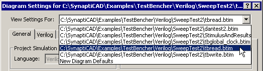
•The View Settings For box allows you to quickly view the settings for different timing diagrams in the project. The New Diagram Defaults sets the options for new diagrams that are created for the project. |
The General Tab
The General Tab in the Diagram Settings dialog controls code generation features for non-language specific items, such as Verbose settings and the default actions for samples.
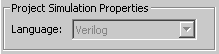
Project Simulation Properties
•Language controls the generation language for timing diagram. The language choices depend on what languages have been licensed for use with TestBencher. TestBencher can generate Verilog and VHDL testbenches. |
|
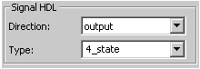
Signal HDL
•Direction sets the default signal direction for new signals. For more information on signal directions, see 2.3 Waveform Colors and Bi-Directional Signals. •Type determines the default SynaptiCAD signal type for new signals. These language independent types are covered in the Timing Diagram Editor manual Section 4.4 Export VHDL and Verilog test benches. |
|
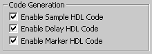
Code Generation
•The three check boxes in the General tab allow you to toggle whether HDL code generation is enabled for samples, markers and delays. |
|
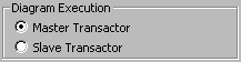
Diagram Execution
•These settings control the default execution process for the current diagram ( see Section 7.2: Master and Slave Transactions). |
|
•The Master Transactor type runs a single time, and can either block the execution of other transactors or it can be executed concurrently. An abort method is also provided for Master Transactors. •The Slave Transactor type runs in a looping mode until it is stopped with an Abort method. Slaves can either execute concurrently or block other transactions while they are looping. |
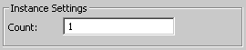
Instance Settings
•The Instance Settings are used to specify information for Pipelining Transactions (see Section 5.8 Pipeline Markers). The Count determines the number of instances of a transaction. These instances will be automatically instantiated in the test bench. |
|
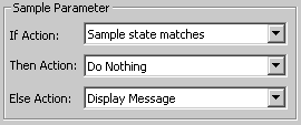
Sample Parameter
•These controls defines the default if condition and subsequent actions for new samples. For more information, see Chapter 3: Transaction Samples. |
|
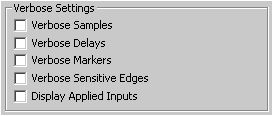
Verbose Settings control debugging output:
•Verbose Samples display when a sample has been triggered to run, when its window has been entered, when it triggers another sample or delay, and when it causes the diagram to restart. •Verbose Delays display when a delay starts, when a conditional test fails (causing the delay to be disabled), and when a delay makes a signal assignment. |
|
•Verbose Markers display their name, type, and the simulation time. Markers that trigger loops or simulation run time events also display when they start and what they are doing. •Verbose Sensitive Edges display when the sequence verification starts, when an edge is detected on a sensitive signal, and when an unexpected edge occurs. •Display Applied Inputs displays the values of input parameters that are passed into calls for the selected transactor. |
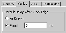
Cycle Based Settings (Language specific)
•This setting affects code that is generated for signals that are clocked . If Fixed is selected, then the amount of time specified is the delay after the clock edge before events occur. If As Drawn is specified then the length of the delay is dependent upon the time at which events on the signal are drawn relative to the clocking edge. |
|
•Early Versions of TestBencher Pro: This option is a direct replacement for the Include Time Delays option in previous versions of TestBencher. Previous projects will be converted as follows: •Include Time Delays ON => As Drawn •Include Time Delays OFF => Fixed to 0 |
Code Generation (VHDL Only)
•The Enable Abort Code checkbox allows you to toggle whether or not abort code will be generated. |
|
The biggest advantage for turning off this code generation is that the amount of code for each diagram will be reduced. The disadvantage is that certain features will be disabled because they rely on the abort code to function. These features include abort transaction apply call, end diagram marker, end diagram sample conditions, diagram timeouts, and delay timeouts.It is expected that this feature will be used mostly for limited testing or for diagrams that do not need an abort. The global clock diagram, for instance, should never have the abort code turned off or you would have to manually end the simulation.
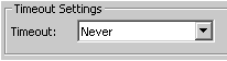
Time-out Settings (Language-Specific)
•A transaction timeout will aid in the prevention of an endless wait condition occurring in a timing transaction. |
|
•The time selected as a time-out duration is measured in diagram lengths for an individual diagram. For instance, a diagram whose entire execution should be complete in 150ns could have a time-out duration of 150ns, 300ns, 450ns, etc. |
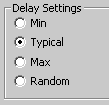
Delay Settings (Verilog & VHDL)
•The delay settings determine how delays will be computed during diagram code generation. This setting determines which delay value is used in min:typ:max expressions. The random setting allows a random value to be computed from within the range of the min and max specified for the delay. |
|