2.3 Waveform Colors and Bi-Directional signals |

|

|
|
2.3 Waveform Colors and Bi-Directional signals |
|
|
2.3 Waveform Colors and Bi-Directional signals |
|
|
|
2.3 Waveform Colors and Bi-Directional signals |
|
|
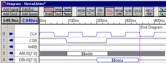
Signals with a direction of output or internal have black waveforms, and signals with a direction of input have blue waveforms. Bi-directional signals with a direction of inout will be drawn with mixed black and blue segments to indicate which segments will be driven by the transactor and which are inputs to the transactor. In the diagram below, CLK is an input to the diagram, so its waveform is blue and the direction icon points to the right. The next three signals are outputs of the timing diagram (they will drive the MUT) and have black waveforms. The DBUS signal is bi-directional signal with mixed black and blue segments.
Setting Direction on Waveform Segments of a Bi-Directional Signal:
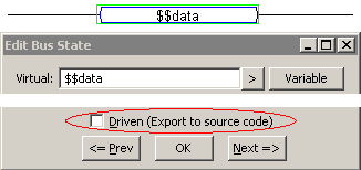
Each waveform segment on a bi-directional (inout) signal has a Driven property that determines whether the segment is an output or input of the testbench. By default, each segment has a direction of output so the waveform will draw as a black signal. If a segment is drawn using a tri-state graphical state, then the segment will not drive the MUT regardless of the Driven property setting. However, when the transactor needs to test the value coming back from the MUT, the expected waveform segments need to be inputs to the testbench. To change a segment to be an input segment (un-driven):
•Double-click on a waveform segment to open the Edit Bus State dialog. •Uncheck the Driven check box. This indicates that the test bench does not drive this segment; this segment will be an input to the test bench. |
|
•Click OK to close the dialog or use <Alt>-N or <Alt>-P (or the Next or Previous buttons) to edit other segments on the same signal. The segment for which you unchecked the driven flag should now be colored blue. |