2.4 Waveform States with Variables and Conditions |

|

|
|
2.4 Waveform States with Variables and Conditions |
|
|
2.4 Waveform States with Variables and Conditions |
|
|
|
2.4 Waveform States with Variables and Conditions |
|
|
The graphical state of a waveform segment controls the value of the segment in the generated test bench code, except for valid segments. Waveforms with a graphical state of valid need to be driven to a distinct value during simulation. Using the Edit Bus State dialog, you can hardcode in a value, choose an existing variable in the timing diagram to drive the state, or in TestBencher define a state variable that can be passed into the transaction when it is applied. State values can also vary based on a conditional expression. If a waveform segment is drawn with a graphical state other than valid, that graphical state will override any other state information entered through the Edit Bus State dialog.
Use the Edit Bus State dialog to edit the state of a valid signal segment:
•Double click on the segment of the signal to open the Edit Bus State dialog. |
|
•The Virtual edit box accepts values, variables, and Boolean equations that meet the format shown in Appendix C: Language Independent Operators. For example, $$addr+@increment is an acceptable equation for the Virtual edit box. |
Hardcode a state value:
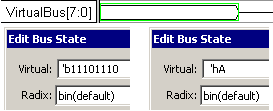
Buses (multi-bit signals) use one of two methods to generate code. First, if a segment's value begins with a 'b or 'h then it is assumed that the number is a binary or hexadecimal number and the number will be translated to the appropriate VHDL or Verilog bus value (regardless of the radix of the signal). If the extended state value does not start with 'b or 'h, then the value is written out as it was entered, without any translation. This means that if a state has a value of 10 and a radix of Hexadecimal, the effective value of the segment is 16 decimal. And if a state has a value of 10 with a radix of Binary, the effective value of the segment is 2 decimal.
•Type the value in the Virtual edit box. •Since this signal has a radix of binary, the `b11101110 is equivalent to entering just 11101110. •If you entered 'hA into an 8-bit binary signal, the value would be converted to 00001010. The program automatically left pads missing bits. |
|
Use a Diagram Level Variable to define the state during simulation:
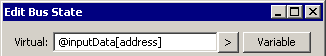
Diagram level Variables are defined using the Classes and Variables dialog as shown in Section 6.1: Variables. Both TestBencher and the Reactive Test Bench option support Diagram-level variables. The type and size are controlled by the user during the declaration of the variables, so they require a little more setup work. Also diagram-level variables can be conditionally driven by different sources like samples and signal states within the timing diagram during simulation as well as being passed into the diagram.
•Either type in a variable name with an @ prefix to indicate it is a diagram level variable |
|
•Or use the > button to display a list of variables, then pick one from the list to insert it into the Virtual box. |
Use State Level Variable to define the state when the transaction is applied (Test Bencher Only):
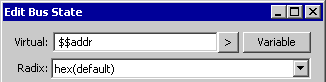
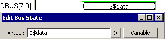
TestBencher state variables can be quickly defined in the Edit Bus State dialog by typing in a variable name that begins with two dollar signs like $$addr. State variables are automatically added to the parameter list for the transaction call. The type and size for these variables are determined by the signal that is being driven. Each time the transaction is called, a new state value can be passed into the variable. The same state variable can also be used on several signals and the maximum size will be determined by the min and max of all of the signals used. For example, if $$addr appears on SIG0[3:0] and SIG1[12:9], then the $$addr will have a size of [12:0].
•Type the variable name using a $$ prefix into the Virtual box. |
|
Do NOT use Parameter Variables to drive signal states:
Parameter based variables from delays, setups and holds should not be used to drive waveform states, because their type is fixed to hold time values, not state values.
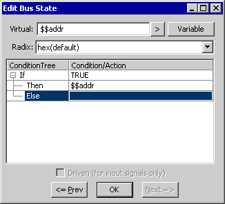
Conditionally Drive a state value:
State values can be conditionally driven based on events and states that occur during simulation. The Edit Bus State dialog contains a Condition Tree that can be used to build conditional strings for the state value. If the state tree is not modified, the value will be unconditionally driven to the value in the Virtual edit box. The driven state can be made conditional by adding a condition to the State Condition tree.
•Double-click on the segment that is to be conditionally driven to open the Edit Bus State dialog. •Right-click on the If row and choose Add Condition from the context menu to open an edit box or double click in the Condition/Action column of the If row. |
|
•Type the text for the condition. The condition must be written in the generated language of the transactor and it must equate to a Boolean equation when evaluated during simulation. |
|
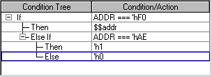
•Next, add the state values to the Then or Else rows by right-clicking choosing Add Variable or Add State menu option. Or double-click in the Condition/Action column and edit the state. •Optional: Complex conditionals can be created using the Add If...Then...Else context menu. This option is available for any existing Then or Else row. Selecting this option causes a nested If...Then...Else to be added to the branch of tree that was selected. |