2.5 Simulated Signals |

|

|
|
2.5 Simulated Signals |
|
|
2.5 Simulated Signals |
|
|
|
2.5 Simulated Signals |
|
|
Signals can be defined using a Boolean equation of other signals in the diagram. These are quite useful for modeling glue logic in slave transactors. The embedded simulation engine properly simulates multi-bit signals, making it easy to model common interface logic such as configuration and mode registers. The simulator also uses true min/max timing models so that the resulting simulated signals can propagate uncertainty delay through the timing diagram. This feature is not supported in WaveFormer Lite with Reactive Test Bench Generation Option.
Code Generation for Simulated Signals:
Only signals that have a direction of output or internal will generate a Boolean and Registered logic code within the test bench.
Define a Signal's waveform using an Equation:
There is an entire chapter in the Timing Diagram Editors manual that explains in detail all of the requirements of the Simulated Signals feature. See Chapter 4 Simulated Signals. This is just a quick introduction.
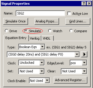
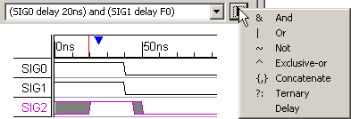
•Double click on a signal name to open the Signal Properties dialog. •Select the Simulate radio button to allow the signal to be re-simulated each time an input signal is changed. •Enter a Boolean equation and check any other attributes for the simulation. •The signal will start to simulate as soon as an equation is entered (if you are in Auto Run and not Debug Run mode). Simulated signals waveforms are drawn in purple. If the waveform is grey there is an error in the equation, see the error section in Chapter 4 Simulated Signals of the Timing Diagram Editors manual. |
|
Syntax
The Boolean Equation edit box accepts Boolean equations in VHDL, Verilog, and SynaptiCAD's enhanced equation syntax. All signal names are case sensitive.
•The quick fill box contains all of the SynaptiCAD operators. |
|
•The delay operator takes a signal on the left and a time or parameter name on the right. If a parameter is entered then the equation will simulate using true min/max timing and puts grey uncertainty regions on the simulated signal. •The delay operator can also be made to simulate min-only or max-only simulations by selecting the Options > Diagram Simulation Preferences menu to open the dialog and then choosing the appropriate setting from the Timing Model list. |