9.7 Diagram Properties dialog |

|

|
|
9.7 Diagram Properties dialog |
|
|
9.7 Diagram Properties dialog |
|
|
|
9.7 Diagram Properties dialog |
|
|
The Diagram Properties dialog sets properties that that are saved in the timing diagram BTIM file and affect all projects that use the diagram. These include the cycle based settings and the include files lists. Changing these properties can break or dramatically change the way the diagram works during simulation. Other diagram settings that are saved in the project HPJ file and only effect the generation of the code (not the operation of the diagram) are edited through the Diagram Settings dialog as discussed next in Section 9.8: Diagram Settings Dialog (TestBencher only).
To edit the Diagram Properties:
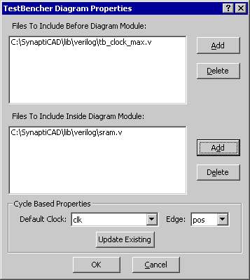
•Open the diagram for which you will be changing the properties. •In the Diagram window, right-click in the signal label area and choose TestBencher Diagram Properties from the context menu. This will open the TestBencher Diagram Properties dialog. |
|
Including HDL Code Library Files
If you have external code modules that you want to make available to the transaction then you can use the interface in the Diagram Properties dialog to make that code available. Files can either be included before the transaction, using the equivalent of the Verilog include statement, or files can be included inside the module. The method for including code within the transaction varies by language. If possible the code is included using something like the include statement and if that concept is not supported then the code is echoed within the transaction. If you have HDL functions or tasks that you would like to write and use within a transaction then use the Class Methods dialog as discussed Section 6.3: Class Methods. Class Methods is a newer interface that is more flexible and it makes it easier to modify the code and parameters of the functions. To Add an HDL Code Library File to the Diagram:
•Click the Add button to the right of the appropriate list box to open a file dialog that lets you browse for the include file. Click Open to close the file dialog. |
Although the code generation for Verilog and VHDL will treat the file lists from this dialog differently, the file selection process for the languages is the same in this dialog.
Cycle Based Properties
The Cycle Based Properties control how clocked signals and events are generated. These settings provide default clocking signals and edges to be specified for a diagram. This area also allows existing signals and parameters to be updated to a new clocking signal and edge.
•The Default Clock and Edge settings provide default values for the clocking signal and sensitive clock edge in a diagram. •The Update Existing button is used to update all signals, samples, delays and anything with a clocking signal defined to the currently selected Clock and Edge/Level. |