5.8 Pipeline Boundary Markers (TestBencher Pro Only) |

|

|
|
5.8 Pipeline Boundary Markers (TestBencher Pro Only) |
|
|
5.8 Pipeline Boundary Markers (TestBencher Pro Only) |
|
|
|
5.8 Pipeline Boundary Markers (TestBencher Pro Only) |
|
|
In TestBencher Pro, Pipeline Boundary Markers can be used to create pipelined transactors. These markers will automatically create a semaphores for each critical region (if the semaphores do not already exist in the project). A critical region is created for each stage of the pipeline. Loop markers can be placed within a critical region - but only if the complete loop is inside the region. In other words, the loop cannot overlap the pipeline stage - it can be entirely inside the stage or entirely around the outside of the stage.
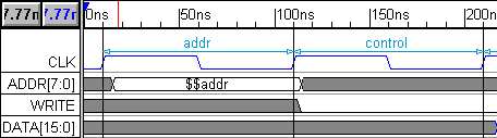
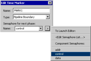
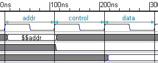
The Semaphore Name specified in the Marker Properties dialog represents the next pipeline stage and is displayed in the diagram between the start and end boundaries of the stage. The next Pipeline Boundary marker in the diagram (either the start of the next stage, an End Boundary pipeline marker or and End Diagram marker) represents the end of the stage. In the diagram above, for instance, the first marker is a Pipeline Boundary marker with addr selected as the semaphore. This stage is ended by the control Pipeline Boundary marker - which also starts the control stage. Section 10.1: Pipeline Transactions shows an example of a project that has different timing diagrams that all share the same pipeline.
To Create a New Pipeline Stage:
You must create at least two markers in the same clock domain (see Section 2.9 Transactor Clock Domains and Waveform Code Generation). That means the beginning and ending markers should be attached to the same edge type of the clock signal or both attached to times.
•First, place a marker at the time or edge where the stage should begin. Double-click the marker to open the Marker Properties dialog. •Choose Pipeline Boundary from the type box. •Enter the name of the stage in the Semaphore for next phase box or use the > button and <Edit Semaphore List> to open the Semaphore List dialog as shown in the previous section. •Close the Marker dialog. |
|
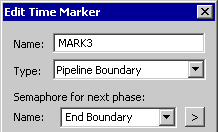
•Place a second marker at the time or edge that will end the pipeline stage. This marker must be one of the following types (otherwise a start stage without and ending marker for the stage will produce an error): |
•Either another Pipeline Boundary with either the Semaphore for Next phase of End Boundary (if it's the last stage in the pipeline) or the name of the next adjacent stage. |
|
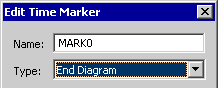
•Or an End Diagram marker which automatically ends the stage. This is a nice feature to use when the last pipeline stage is the last event in the diagram. |
|
•A properly drawn pipeline stage will have a blue line between the pipeline markers that lists the name of the stage. |
|
Instance Count:
The Instance Count of a diagram represents the number of instances of the transactor that are created during simulation (each transactor instance can run simultaneously). TestBencher will automatically set the Instance Count for the diagram during generation to the number of pipeline stages in the diagram. This setting can be overridden, but it is not normally necessary to do this. Should this setting be overridden, the pipeline depth must be less than or equal to the Instance Count of the timing diagram. The diagram Instance Count is set in the Diagram Settings dialog.
•Select Project > Default Diagram Settings... from the main menu to open the Diagram Settings dialog. •The Count determines the number of instances of a transactor. These instances will be automatically instantiated in the test bench. |
|