10.1 Pipeline Transactions |

|

|
|
10.1 Pipeline Transactions |
|
|
10.1 Pipeline Transactions |
|
|
|
10.1 Pipeline Transactions |
|
|
TestBencher Pro supports Pipeline modeling using markers and semaphore variables. When you enter a pipeline marker in one timing diagram, its semaphore variable becomes a project level variable that can be used in other timing diagrams in the same project. When a transaction enters a pipeline stage, it decrements the associated semaphore so that any other transaction that attempts to enter that particular pipeline stage will block until the original transaction exits the stage. Section 5.4: Pipeline Boundary Markers describes how to insert pipeline stages into a timing diagram.
Setup the Pipeline Stages in the Timing Diagrams
The Pipeline project in the SynaptiCAD>Examples>TestBencher directory shows an example of pipelined read and write timing diagrams.
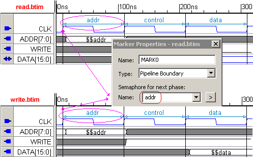
Both the read and the write diagram have three pipeline stages defined by markers with the same semaphore names: addr, control, and data. The pipeline stages are automatically displayed using a blue arrow line and the semaphore name centered between the entry and exit to the stage.
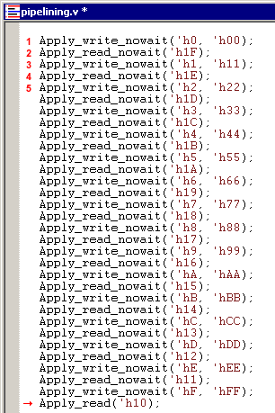
Use Apply-No-Wait transaction calls in the Sequencer Process
In most of the examples in the manual, we call master transactions using a regular Apply call, which blocks subsequent transaction calls until the current transaction is completed. However, when using pipelines, you will want the transactions to run currently and block only at the pipeline markers since the transaction durations overlap in time. To do this, just check the Apply No Wait radio button in the Insert Diagram Calls dialog (see Step 5: Define Sequencer Process).
•Since all of the transactions calls are Apply_nowait, all of the transactions will start at the same time and queue up in the order they were called. •Line1: the first write call will execute and grab the addr semaphore, block all the other transactions from entering the pipeline stage. •Line 2: when the first write transaction moves into the control section, it releases addr and the next transaction (the read in line 2) grabs addr and blocks all others. •When the first write moves into the data pipe, it will release control and allow the next transaction to enter the control stage. This process will continue until all of the transactions have passed through all three stages of the pipeline. •Note that the final apply call does not need to be a NoWait call. In fact, if it's the last apply call in your sequencer process, you should probably use the "blocking" call version of the Apply, so that the sequencer is blocked from finishing until the last transaction completes. For example, note the Apply_read instead of Apply_read_nowait at the end of the example sequencer. |
|
Semaphore Implementation of Pipeline stages
A semaphore is created for each stage of a pipeline. The semaphore is set with an initial count of 1, effectively making it a mutex (a mutually exclusive semaphore that enables only one transaction at a time to enter the pipeline stage).
When a transaction attempts to enter a pipeline stage, it makes a semaphore Wait call to see if it can enter the stage by acquiring the mutex. If it fails, it will wait until the transaction currently executing that stage completes and releases the mutex. When the transaction finally does enter the stage, it will make a Post call to release the mutex for the previous stage it was in (assuming this isn't the first stage in the pipeline). Below is pseudocode for the semaphore calls made in the read and write diagrams discussed above:
addr.Wait() //attempt to grab the addr mutex,
//and block until we get it
perform addr stage
control.Wait() //wait until we can enter the control stage
addr.Post() //only allow other diagrams to enter addr stage
//after we have left it
perform control stage
data.Wait()
control.Post()
perform data stage
data.Post() //last stage in the pipeline, so we don't
//need to wait for a new stage before releasing
Note how the wait for the next sempahore must happen before the post of the previous semaphore. This detail is automated when using Pipeline Boundary markers. For each semaphore needed, a tbfifosemaphore module is instantiated in the top-level component model. That allows the semaphore to be shared between different diagrams in the same project. Currently there is no wait to share a semaphore across multiple projects.
Verilog Specific Details:
The definition of the tbfifosemaphore module can be found in lib\verilog\tbfifosemaphore.v file. This module's purpose is to preserve the order in which diagrams are waiting for a given semaphore. This module defines 3 procedures to access the semaphore: GetPidIfNecessary, WaitComplete, and Post.
Here is an example of what is generated for a Wait semaphore call.
//Waite for Semaphore: pipelining.pipeline_phase_control
tb_pid = pipelining.pipeline_phase_control.GetPidIfNecessary(0);
if (tb_pid != 0)
begin
while(pipelining.pipeline_phase_control.resume_pid != tb_pid)
begin
@(pipelining.pipeline_phase_control.resume_pid);
end
end
pipelining.pipeline_phase_control.WaitComplete(tb_pid);
GetPidIfNecessary will return 0 if the semaphore's count is > 0, which means that the transaction doesn't have to wait for the semaphore to be posted (i.e. incremented). If GetPidIfNecessary returns a non-zero number then thta number represents the resume_pid to wait for. When a tbfifosemaphore is posted it will set the resume_pid to the next waiter in line (if there is one). Once the wait is complete, WaitComplete is called on the tbfifosemaphore which will decrement the count. When the transaction wants to release the semaphore, it simples calls Post which will increment the semaphore and set the appropriate resume_pid if necessary.