Step 5: Define Sequencer Process |

|

|
|
Step 5: Define Sequencer Process |
|
|
Step 5: Define Sequencer Process |
|
|
|
Step 5: Define Sequencer Process |
|
|
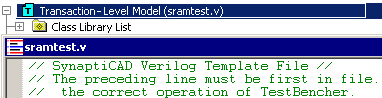
TestBencher generates all of the top-level code for the test bench into the Transaction-Level Model (TLM) file, including the code that instantiates the model under test and connects it to the test bench model. This is a special template file that will contain both generated code and user-defined code. Any code that appears between a beginning-comment an end-comment will be regenerated each time the test bench is made, so this code should not be edited by hand. The following is an example of such a code block for a Verilog test bench:
// $DataStructureInstantiationsForAllDiagrams
...
// End $DataStructureInstantiationsForAllDiagrams
The TLM file also contains the Sequencer process that controls the sequencing of transactions during the simulation of the TLM. The Sequencer process is the place where you typically add function calls to apply transactions to the model under test.
If you need more complex transaction sequencing than is possible using simple Apply calls, you can enable generation of a Transaction Manager which allows transactions to be read from files, randomly generated, or placed in one or more queues where they can be scheduled for future execution. Chapter 7: Transaction-Level Model and Transaction Sequencer describes the sequencer process, the transaction manager, and the TLM template file in detail.
Open the TLM file and find the Sequencer Process
•Double-click on the Transaction-Level Model folder in the Project window to open the TLM template file. |
|
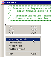
•Scroll down in the template file until you find the comment block that contains the Sequencer Process. The comment will contain the following text: |
//***********************************************************
// Transaction Sequencer - After this comment, define how to
// apply transactions to the model under test using:
Use the Insert Diagram Subroutine Call dialog to make Transaction Calls:
•Click in the Editor window just below this comment at the place that you want to add a transaction call. •Then right-click and select the Insert Diagram Calls... menu option from the context menu. This will open the Insert Diagram Calls dialog with a list of statements that represent each of the timing transactors that have been added to the project. |
|
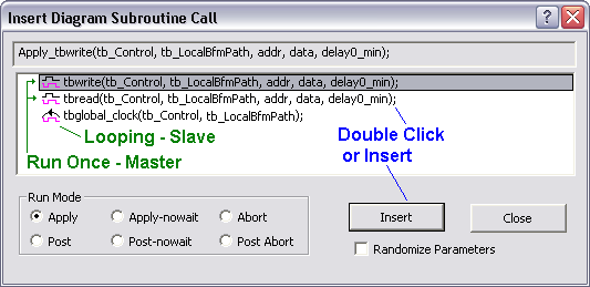
•Arrange the windows so that you can see the dialog and sequencer editor at the same time. •Select a timing diagram name and a run mode, then press the Insert button to insert the code into the editor. •The Run Mode radio buttons will default to Apply for Master transactions to run them in a blocking mode. For Slaves, the default is Apply-nowait to run the transaction concurrently with subsequent apply calls. The Abort function will stop a transaction during mid-execution and is typically used to stop the execution of a slave transaction (which otherwise loops forever). For more information see Section 7.1: Template, Sequencer, and Transaction Calls. •A Post call schedules a transaction for future execution by placing it into a Transaction Manager queue (instead of immediately applying the transaction). The Transaction Manger must be enabled as described in Section 7.3 Transaction Manager Overview for these calls to operate. •The Randomize Parameters box changes Apply and Post calls so that the data parameters of the transaction will be randomly generated instead of being specified in the procedure call. For details, see Section 7.7 Randomizing Transaction Inputs. •Notice that the Apply statement was inserted at the same line as your cursor. The Insert Diagram Call dialog is a modeless dialog, so it can remain open while you perform other actions. If the applied transaction contains variables, then both a comment and a code line will be added. Edit the code line to apply the real parameters and leave the comment line 'as-is' to document the parameter names. Below is an edited example of an apply call in Verilog. |
// Apply_tbwrite(addr, data, delay0_min_bits)
Apply_tbwrite('h55, 'hee, $realtobits(delay0));