Step 4: Create the Timing Transactor Diagrams |

|

|
|
Step 4: Create the Timing Transactor Diagrams |
|
|
Step 4: Create the Timing Transactor Diagrams |
|
|
|
Step 4: Create the Timing Transactor Diagrams |
|
|
TestBencher generates a transactor for each timing diagram in the project that represents a reusable interface specification of the bus-functional model that you are creating (e.g., read cycle, write cycle, interrupt cycle). These transactors are modules for Verilog, entity/architecture pairs for VHDL and classes for TestBuilder. Regardless of the language, the transactors use the same general architecture. And in all languages, the transactors have a similar functional API that can be used to trigger them (diagram apply calls). The tutorials and Chapters 2-6 describe how to draw the timing diagrams and control the generated code. When a new timing diagram is created, it will contain all of the signals and properties of the Template Diagram. Do the following steps for each timing transactor that you want to call in the test bench:
Create a new timing transactor:
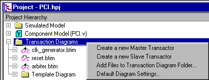
•In the Project window, right-click on the Transaction Diagrams folder and choose one of the Create a new ... Transactor menus. This opens a file dialog to create and save the diagram. •After saving the diagram, it will be added to the Transaction Diagrams folder. The diagram will contain the template signals and properties. |
Master Transactors are transactions that run once and then stop and are represented by the waveform icon. Slave Transactors are transactions that will loop continuously until they receive an abort call and are shown by icon with a waveform and a loop-back line. Slave transactions are usually started at the beginning of a test bench and run until the test bench completes. |
•Create a timing diagram by sketching the waveforms using the Timing Diagram Editor. Optional objects such as samples, markers, delays, variables, and class methods will be discussed in more detail later in this manual and are demonstrated in the tutorials. See chapters 2-6 for how to create the transactions. •Select the File > Save Timing Diagram menu option to save the timing diagram and generate the HDL code. Each time you save a timing diagram, new code is generated for it. |
Change to and from Slave and Master:
The Slave and Master setting for a timing diagram affects the way code is generated for the timing transaction. After the timing diagram is created, you can change to the other setting by doing the following:
•Right click on the timing diagram name in the Project window and choose Diagram Settings from the context menu to open the Diagram Settings dialog. •Then check either the Slave Transactor or Master Transactor radio button. |
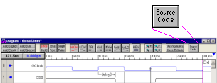
View the generated HDL source code:
Since the source code for a timing diagram is regenerated each time it is saved, you should not make any manual changes to the code. However, it is sometimes useful to see how the low level code changes based on the constructs that are placed in the diagram.
•Click the Source Code button to open an editor and view the code. |
|