2.9 Transactor Clock Domains and Waveform Code Generation |

|

|
|
2.9 Transactor Clock Domains and Waveform Code Generation |
|
|
2.9 Transactor Clock Domains and Waveform Code Generation |
|
|
|
2.9 Transactor Clock Domains and Waveform Code Generation |
|
|
Inside each timing diagram there may be one unclocked process and several clocked processes. A clocked process is created for each clocking domain in the diagram to drive signals and trigger parameters (Delays, Samples, Holds, Setups, Markers) that are synchronous with the given clock. Each domain will run in parallel (concurrently) once the diagram is started.
Typically, there will only be one clock domain in a timing diagram. But, if you have multiple domains in the diagram, then it’s important to know what is placed in each domain if you have looping or blocking parameters. For example, a Marker loop that is attached to the falling edge of CLK will only loop around items that are also in the CLK_neg clock domain. Items that are in the unclocked domain wouldn't get placed into this loop. Also, items that can potentially block a process (Samples, Markers, Sensitive Edges) will only block the clock domain that they are placed in. The following sections will go into more detail on how blocking and looping constructs work.
Overview of Graphical constructs and their clock domains:
Construct Type |
Clocking Domain |
Signals |
Clock and Edge of signal (Signal Properties dialog) |
Sensitive Edge |
Clock and Edge of signal that contains sensitive edge |
Samples |
A sample's clock domain is the process that triggers it. See the table below to determine a sample's triggering process. |
Delays attached to edge |
If not unclocked, then Clock and Edge in Delay dialog. Otherwise, the starting edge of the delay sets the clock domain. |
Setups |
Signal and edge that is pointed to by the Setup |
Holds |
Signal and edge that is pointed to by the Hold |
Markers attached to edge |
The relative edge sets the clock domain |
Markers attached to time |
Unclocked |
Waveform Code Generation:
The code that is generated for a waveform depends on three things: how it is drawn, the clocking domain, and the Default Delay After Clock Edge control in the Diagram Settings dialog.
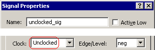
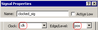
•For unclocked signals, the waveform events will be generated at the times they are drawn. •To check the clocking domain of a signal, double click on the signal name to open the Signal Properties dialog. If the Clock property is set to Unclocked, then it is unclocked. |
|
•To make a signal clocked, set the Clock and the Edge/Level setting in the Signal Properties dialog (double click on the signal name to open the dialog). The Clock can be any signal or clock in the diagram. |
|
•For the Reactive Test Bench Option, a clocked signal will generate code such that the clocked signal's edges will sync up to the active edge on the "clock" signal. |
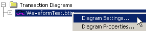
•For Test Bencher Pro, a clocked signal's code also depends on the controls in the Diagram Settings dialog. Right click on the diagram name in the Project window and choose Diagram Settings from the menu. |
|
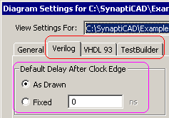
•Choose the language tab of your generation language. •Fixed 0ns, means that the edges of a clocked signal will sync up to the active edge of the clock. If there is a delay, like 10ns, then the clocked signal's edges will be driven 10 ns after the active clock edge. |
|
•As Drawn will delay the edges of the clocked signal relative to the the clocking edge based on the distance drawn. For example, if an edge is 5 ns after it's clocking edge, the code will wait for the clocking edge, then further delay for 5 ns before driving the signal edge. Below is the code generated by such a signal: // Synchronize to clocking signal if necessary. @(posedge CLK0); #5; tbench.SIG0_driver <= 1'b0; |
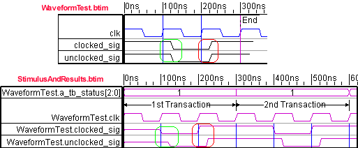
Below is an example of a timing diagram WaveformTest with both a clocked and an unclocked signal. The Default Delay After Clock Edge setting for the diagram is Fixed 0ns. The Stimulus and Results diagram shows the behavior of the test bench during simulation. Notice that the edges on the clocked_sig have moved to the positive edge of the clk signal in the simulated results, and the edges on the unclocked_sig generate code as they are drawn in the original transactor diagram.
Output Clocks (Clock generators)
When creating a clocked test bench with TestBencher, there is usually either one timing diagram that has an output clock or the clock is generated in the MUT code. All of the other timing diagrams use an input clock. This makes it easier to synchronize the transactions during simulation. If you choose a system clock when during the project creation, then TestBencher will create a diagram called SysClock_generator.btim to generate the clock, and also add an input clock to the template diagram (see Step 1: Create a New Project).
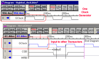
Each output clock has its own process that generates the clock during a simulation. This clocking process is in addition to any unclocked or clocked processes that are used to synchronize signals and parameters. The clock generation process will take into account as many of the Clock Properties as are supported by the generation language.
Blocking Constructs (Sensitive Edges, Samples, and Markers)
There are three different types of constructs that can be used to block the execution of a clock domain.
•A sensitive edge will cause its clock domain to wait on the edge, which will block all other items in that same clock domain until the edge is detected (see 2.6 Sensitive Edges - a Blocking Construct). •A Sample that has the blocking setting checked (see Section 3.3: Samples that Block Clock Domains) will block its clock domain until the sample completely finishes, including execution of its then or else action. •And a Wait Until Marker will block its clock domain until the condition specified becomes true. If the marker is attached to an edge it will only check for the condition at each clock edge of the clock domain (see Section 5.4 Wait Until Markers). |