2.8 Adding Signals Manually |

|

|
|
2.8 Adding Signals Manually |
|
|
2.8 Adding Signals Manually |
|
|
|
2.8 Adding Signals Manually |
|
|
Most of the testbench signals will be automatically added by extracting the signal information from the model under test using the techniques that are discussed in Step 3: Extract MUT Ports into Template Diagram. Signals can also be added manually by using the buttons on the signal button bar. Certain types of signals like compare and internal signals are always added manually.
Alternative: TestBencher Pro Sub-Projects
Since the generated bus-functional model provides stimulus and monitors simulation outputs of the MUT, the output signals of the bus-functional model have to match the signals that exist in the MUT. If the signals in the timing diagrams are named the same as in the MUT, then the matching will be automatic. If the signal names do not match, then you will have to create a sub-project and use the Signal and Ports dialog to define the signal mapping as covered in Section 9.1 Sub-Projects.
To add a Signal, Clock, Bus or Spacer:
•Press one of the Add buttons in the timing diagram editor to add a signal of that type. Spacers are just for making the timing diagram look nice and will not generate code. |
|
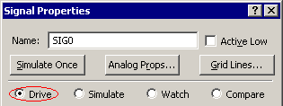
•Double click on the name of the new signal to open the Signal Properties dialog. •For testbenches, the Name must exactly match the signal name in the MUT. If it is an internal signal, then the name can be any valid name supported by the generation language. |
|
•Drive is the type of signal that can act as an input or output from the testbench. Compare signals are covered in the Timing Diagram Editors manual Chapter 9: Compare and Transaction Tracker Options. Simulate signals are used to model simple glue logic such as Boolean equations and registers. Watch signals are used by the BugHunter interface to display simulation results. |
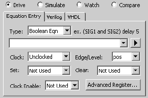
•Set the Clock and Edge/Level settings if the signal is to be a clocked signal. In TestBencher, these will be automatically set by the Project Wizard options, however, you can pick a different system clock signal and edge using these controls. TestBencher users can also change the default clock using the Diagram Properties clock. •You can also use a Boolean equation to describe the waveform of the signal as shown in the Timing Diagram Editor manual Section 2.5: Simulated Signals. |
|
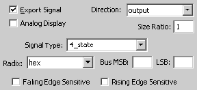
•Edit the Signal Type. This box uses SynaptiCAD's language independent types (that convert to the closest VHDL or Verilog type) and you can also type in VHDL user defined types. •Edit the signal size using the MSB and LSB boxes. |
|
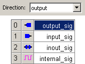
•Edit the Direction using the drop down list box. The following directions are available: •Output indicates that the signal is an output from the diagram transactor (i.e. an input to the model under test). |
|
•Input indicates that the signal is what you expect the model under test to generate during simulation (these signals are inputs to the timing transactions, driven by the model under test). In the timing diagram, Sample parameters usually end on an input signal, indicating that the input signal should be checked for an expected value at that point on the signal. •Inout indicates that the signal is bi-directional (see 2.3 Waveform Colors and Bi-directional Signals). Inout signals contain driven and un-driven signal segments. Driven segments act like signals of type output. •Internal indicates that the signal will only be used internally to the diagram transactor. These are typically used to compute intermediate values that don't directly drive the model under test. •For Clocks, the clock period, duty cycle, and clock offset can be changed by either clicking on the Clock Properties button or by double clicking on the clock waveform. |
The default signal direction, clock domain, and language type for new signals can be set from the Diagram Settings dialog (see Section 9.8: Diagram Settings Dialog - Overview for more information).