Chapter 2: Timing Transactor Basics |

|

|
|
Chapter 2: Timing Transactor Basics |
|
|
Chapter 2: Timing Transactor Basics |
|
|
|
Chapter 2: Timing Transactor Basics |
|
|
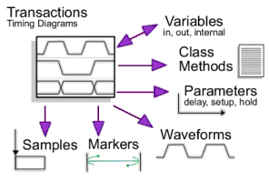
TestBencher uses graphical timing diagrams to generate reusable timing transactors (e.g., read cycle, write cycle, interrupt cycle) that can be called by a top-level test bench and applied to the model under test. Reactive Test Bench Option uses a single timing diagram to generate test benches. This chapter covers how to draw signals in a timing diagram, specify state values and clocking domains, verify sequences with sensitive edges, and other waveform related features. The next few chapters cover other graphical elements in the timing diagram such as samples, markers, delays, setups, and holds, and variables and class methods used to define algorithmic functions.
. 
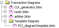
For TestBencher Pro users, the Transaction Diagrams folder in the Project window holds all of the transactors and the template diagram for the project. As shown in Step 3: Extract Ports into Template Diagram and Step 4:Create Timing Transactor Diagrams, use this folder to create new diagrams, open diagrams for editing, and edit the transaction properties including the Master and Slave setting. |
|