Step 2: Create the Reactive Diagram |

|

|
|
Step 2: Create the Reactive Diagram |
|
|
Step 2: Create the Reactive Diagram |
|
|
|
Step 2: Create the Reactive Diagram |
|
|
Next draw the waveforms and other graphical objects in the diagram with the extracted signal information. You will want to read through the following chapters and do the Reactive Test Bench Tutorial to see the kinds of code that you can generate.
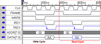
Draw the Stimulus and Expected waveforms:
Chapter 2: Transaction Waveforms and Signals describes how to draw the waveforms. Since this option only supports single timing diagram test benches you can skip section 2.1 which discusses how timing diagrams are initialized. With the single timing diagram test bench, the diagram will initialized when you start drawing stimulus on to the test bench output signals.
Reactive test bench generation also allows the option of creating "clock-based" test benches as well as the "time-based" test benches. Clock-based test benches delay in clock cycles instead of times, allowing the user to change his clock frequency without needing to change his timing diagram. Clock-based test benches are also required when testing using high-speed "cycle-based" simulators. The clock setting is in the Signal Properties dialog of each signal.
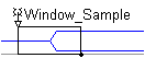
Add Samples (major construct for testing model output):
Chapter 3: Transaction Samples describes how to add graphical Samples to test model output and change what stimulus is applied based on that output. During simulation, the code generated by the samples watch the output from the model under test and compare it to drawn states. The samples can perform a variety of functions such as pausing the simulation to debug a problem, reporting errors and warnings, user-defined actions, and triggering other samples.
![]()
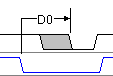
Add Delays, Setups, and Holds:
Chapter 4: Transaction Delays, Setups, and Holds describes how code is generated for these parameters. The Setups and Holds will make code that monitors signal transitions that come back from the model under test during simulation and generate pass-fail reports.
 or
or 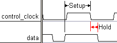
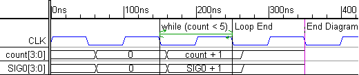
Add Markers:
Chapter 5: Transaction Markers describes how to add graphical Marker lines that can be used to wait for activity from the model under test and/or loop over a section of a diagram. Markers can also be used to call user-written HDL functions and tasks from within a diagram.
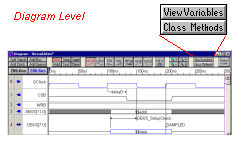
Add Variables and Class Methods:
Chapter 6: Classes and Variables describes how to define variables that can be used by the Reactive Test Bench Generation option.
•Variables can be created using the View Variables button or directly inside certain objects like Samples, Delays, Setups, and Holds. •Functions or Tasks can be embedded into the timing diagram by entering the code into the Class Methods dialog. This code can be called from an HDL Code Marker. |
|
Organizing a Test Bench:
As your test benches become more and more complicated, it will become more difficult to model them using a single timing diagram. At some point, you may wish to upgrade to Test Bencher Pro. All of your timing diagrams will import into TestBencher Pro. Also the Edit > Block Copy can be used to copy sections of a large Reactive Test Bench diagram and then paste them into smaller reusable TestBencher transaction diagrams. We have included a few test bench designs in Chapter 10 that explore how to design test benches with both the reactive test bench option and with TestBencher Pro.