11.6 Testing a Counter Model (Reactive and TestBencher) |

|

|
|
11.6 Testing a Counter Model (Reactive and TestBencher) |
|
|
11.6 Testing a Counter Model (Reactive and TestBencher) |
|
|
|
11.6 Testing a Counter Model (Reactive and TestBencher) |
|
|
Testing a counter with a reactive test bench is a lot easier than it is with traditional stimulus-based test benches. The test bench can be designed with just a small two cycle timing diagram with a loop. Below is an image of a diagram that tests a 32-bit counter.
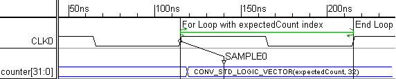
Discussion of the Counter Test Bench:
•Counter Loop: two loop markers surround a clock cycle. The first marker starts the For-Loop and initializes an index variable called expectedCount. Each time through the loop, expectedCount will be incremented. The For-loop is defined in the Marker dialog of the first marker.
•Expected Counter Output: The signal counter is blue to indicate that it is the output of the model under test and an input to the test bench. Each time the counter is incremented we expect the counter model to increment and to be equal to the index of the For-Loop. The SAMPLE0 compares the actual simulation output with the value generated by the test bench. The bus state of the counter signal contains code that defines how the model output should change with each loop. It is language dependent:
VHDL: The image shows a VHDL test bench that converts integer expectedCount to a 32-bit standard logic vector. The CONV_STD_LOGIC_VECTOR is necessary because VHDL does not automatically convert integers to standard logic vectors.
Verilog: The code would just be expectedCount, because the language is able to automatically do the conversion.