10.5 Reading and Writing Serial Data |

|

|
|
10.5 Reading and Writing Serial Data |
|
|
10.5 Reading and Writing Serial Data |
|
|
|
10.5 Reading and Writing Serial Data |
|
|
To read and write serial data, you can use diagram-level variables and manipulate the data coming in or going out of the transaction. The UART (Universal Asynchronous Receiver/Transmitter) project in the SynaptiCAD>Examples>TestBencher directory is an excellent example of manipulating serial data.
Setup Write Diagram to write out one bit at a time:
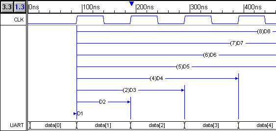
Below is the UART write timing diagram that takes a byte it receives from the top-level project and serializes the data to the MUT.
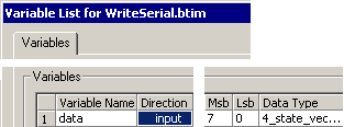
•The diagram-level variable, data, is an input to the transaction. It will hold the byte data to be serialized. Press the View Variables button on the diagram window to open the Variable List dialog |
|
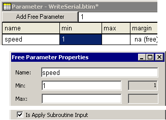
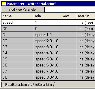
•A free parameter variable called speed determines the number of clock cycles needed to write the bit of data. It was added by pressing the Add Free Parameters button in the Parameter Window. |
|
•Making input the direction of data variable, causes data to become an input parameter to the diagram apply call. •Checking Is Apply Subroutine Input in the speed parameter's Properties dialog causes Speed to become an input parameter |
|
•On each clock cycle (or number of clock cycles) a new data bit is driven to the MUT. The min values of the delays are defined using equations with the variable speed which controls how many clock cycles that they should delay. |
|
The Read Diagram re-packs the serial bits back into a byte:
The read diagram will read in the serial bits and repack them back in to a byte variable that will be exported as an output to the timing diagram. Below are two examples on how to do this. The first uses a series of loops and a signal sample to make the diagram.
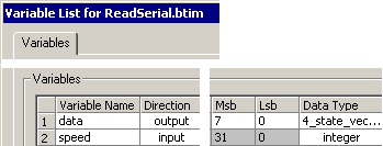
•This diagram has two variables, data and speed that are both parameters to the timing diagram apply call. Press the View Variables button on the diagram window to open the Variable List dialog. |
|
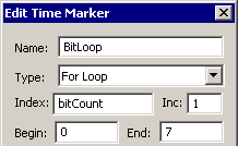
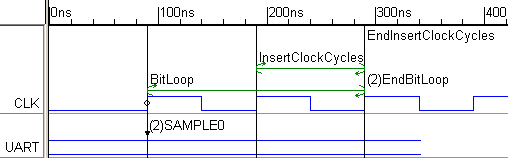
•The BitLoop marker begins a for-loop that counts over the number of bits in the data stream. |
|
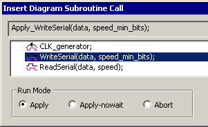
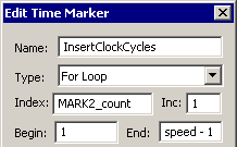
•The InsertClock Cycles marker begins a for-loop that will add in clock cycles based on the speed variable. The speed variable is passed into the write cycle apply subroutine call. |
|
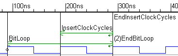
•Notice that the (2) beside EndBitLoop indicates that it triggers after the End Insert Clock Cycles marker. The triggering order is set by double clicking on the edge. The Bit loop surrounds the InsertClockCycles loop. |
|
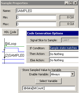
•Sample0 is triggered from the same edge as BitLoop so that both are in the same clock domain. The (2) beside Sample0 indicated that it is inside t he BitLoop (triggers after). •Each time that BitLoop executes, Sample0 will sample the value on the UART bus. Then only thing that Sample0 does is write the bit to the data variable. The bitCount variable is the index variable created by the BitLoop marker. |
|
Another way to design the read UART is to fully draw out the timing diagram.
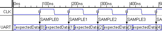
•There is an output variable called data to hold the data coming back from the MUT •There is an an input variable called expectedData that is to compare against the actual data. •Also a parameter variable called speed that determines the number of clock cycles needed to read a bit of data. •On each clock cycle (or number of clock cycles) a new piece of data is read in. The speed variable is used to define the sampling window for each full-expect, blocking sample. At the end of the sample widow, each sample compares the actual data with the expected data and logs any errors. The samples also store the actual data into the correct bit of the data variable. |