10.4 Conditionally Moving Signal Edges (Sweep Tests) |

|

|
|
10.4 Conditionally Moving Signal Edges (Sweep Tests) |
|
|
10.4 Conditionally Moving Signal Edges (Sweep Tests) |
|
|
|
10.4 Conditionally Moving Signal Edges (Sweep Tests) |
|
|
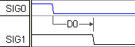
Sometimes it is desirable to move an input signal edge each time it is applied to the MUT. This allows testing the MUT under different timing conditions. Sweep tests can also be performed that move the edge until a setup failure is generated. The SweepTest2 project in the SynaptiCAD>Examples>TestBencher directory shows how an edge can be moved. Make sure to study both the timing diagrams and the Sequencer Code that calls the diagrams to figure out how the code works.
Add a delay that forces the edge that will be moved:
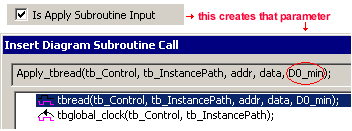
A Delay can be used to move and conditionally trigger signal edges. Each delay creates two variables named delayName_min and delayName_max, which specify either a fixed time or the number of clocking signal edges between two signal transitions. Section 4.1: Delays describes how to add a delay, which is usually added between a blue input signal and the black output signal that will be forced.
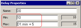
When a Delay has both a min and a max time value, the actual value used at run time is determined by the delay setting in the Diagram Settings dialog (see Section 9.8 Diagram Settings dialog).The delay time can be set to be the minimum value, the maximum value, the average of the min and the max, or a randomly changing value between the min and the max value.
The delay value can be passed into the timing diagram Apply call
•If the delay value will be passed into the timing diagram, check the Is Apply Subroutine Input box in the Delay Properties dialog, to add the delay variable to the timing diagram apply call. |
|
The delay value can be calculated within the timing diagram during simulation
•If the delay value will be calculated within the timing diagram during simulation, enter the min or max times or time formulas like D1.min + 5. |
|
Time formulas can be based on either diagram level variables, variables from other delays, setups, holds or samples, or project level variables that are passed into the diagram. See Chapter 6: Classes and Variables and also the Timing Diagram Editor's Manual Section 2.5: Time Formulas for Clocks and Parameters for information on the syntax of formulas.
Add a Setup, Hold, or Sample to Monitor the transaction behavior as the edge is moved:
For sweep tests you will want to monitor the reaction of the MUT using either a setup, a continuous setup signal, or a sample, depending on exactly what you want to check:
•Graphical setups monitor the distance between two specific edges in a transaction. (Section 4.2: Setups and Holds).
•Continuous setups monitor all of the edge transitions during a transaction between any two signals in a timing diagram. A continuous setup or hold is created using the Advanced Register and Latch Controls in the Signal Properties dialog as described in Section 4.3: Creating Continuous Setups and Holds.
•A windowed, full-expect sample can be used monitor the MUT response. This type of sample checks to make sure that the MUT's signals either transition or stay stable within a window of time (Chapter 3: Transaction Samples).