4.1 Delays |

|

|
|
4.1 Delays |
|
|
4.1 Delays |
|
|
|
4.1 Delays |
|
|
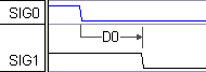
A delay specifies a fixed time or a number of clocking signal edges between two signal transitions. Delays can also conditionally drive their second edge. In TestBencher, the value for the delay time can be passed to the delay code during the simulation. One use of this is to perform a sweep test, where the delay value is progressively increased until a circuit failure occurs.
Delays create two diagram level variables
For each delay in a diagram, two variables are created in the transactor, delayname_min and delayname_max, that can be used in other parameters and in user-defined HDL code statements.
Only Delays triggered by Input signals generate edge-triggering code
Delays with trigger edges on input (blue) signals that force an output (black) signal will generate transactor code that may conditionally drive the output signal's edge. Also, if a delay is part of a chain of delays that has its base delay triggered from an input signal, then the rest of the delays in the chain will generate test bench code. On the other hand, if a delay is put between two output signals and the delay is not part of a chain of delays, then the delay will be evaluated during code generation and the signal transition times will just be hard-coded in the transactor.
Delay Parameter's Clock Domain
Delays are placed in a clock domain based on the same rules that apply to Samples (See Section 3.3 Samples that Block Clock Domains). The only difference is that it is not possible to create a delay that is not attached to an edge. Therefore delays are never triggered directly from the unclocked sequence, but from the clock domain of the edge the delay starts from (i.e. the starting edge of the delay is the triggering edge).
Triggering Edge |
When Delay Activates |
Attached to an edge on an unclocked signal |
Activate if and when the triggering signal edge occurs |
Attached to an edge on a clocked signal |
Activate at next clock edge (not at triggering signal's edge) if a level sensitive check succeeds. The triggering signal is checked against the expected value that the signal transitions to in the diagram. |
Attached to a sample action |
Activates if and when sample condition is satisfied |
Once a delay is activated, then the delay process will wait for the amount of time (or clock cycles) specified in the min or max value of the parameter, and then drive the second edge. For more information, see Section 2.9 Transactor Clock Domains and Waveform Code Generation.
To add a Delay:
•Press the Delay button so that right clicks will add delays. |
|
•Left click on the first transition in time to select it. This must be a blue input signal or an edge within a chain that starts from an input signal in order for the delay to generate conditional code, otherwise the delay just sets edge placement for code generation. |
|
•Right click on the second transition to add the delay. |
|
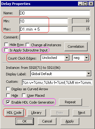
•Double click on the delay to open the Delay Properties dialog. •Enter the min or max times (or time formulas like D1.min + 5). See the Timing Diagram Editor's Manual Section 2.5 Time Formulas for Clocks and Parameters for information on the syntax of formulas. •At simulation time, only one value min, max, or typical (average of min & max) will be used. In TestBencher, the Diagram Settings dialog (discussed in Section 9.8: Diagram Settings Dialog (TestBencher Only)), has the settings that determine which value will be used during simulation. If only one of the two settings has been given a value (min or max), the other setting will internally be given the same value. •Delays can be clocked by specifying a clocking signal in the Count Clock Edges box and an edge type (pos, neg, or both). If a clock is specified, then the min and max boxes will specify the number of edges instead of time values. |
|
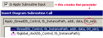
•For TestBencher Pro, the Is Apply Subroutine Input, if checked, generates input parameters to the timing transactor Apply call that can be used to specify the values to use for the min and max settings of the delay. See Step 5: Define the Sequencer Process for more information on the Insert Diagram Subroutine Call dialog. |
|
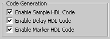
•The Enable Code Generation enables/disable the "edge-triggering" code for this delay. The delay's diagram level variables are created regardless, as these values may be referenced by other parameter's formulas. |
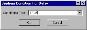
•Press the HDL code button to open the Boolean Condition for Delay dialog. This stores the condition that is checked before the delay drives the second edge. By default, the condition is TRUE (e.g. the default is for the Delay to always cause an edge transition when it's triggering condition occurs). |
|
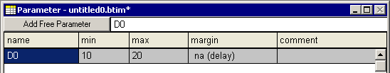
•You can type in the text for a new condition. The condition can be any equation that evaluates to a TRUE or FALSE at simulation time. If the condition is not true after the triggering edge is detected, then the second edge will not be driven. The condition must be written in the generated language of the transaction. •Alternative Approach: If the condition is to be based on state values that occur during simulation, then it can also be done with a delay that is triggered from sample parameter so that the resulting diagram shows the test graphically rather than as a hidden test within the delay's Boolean condition dialog (see Section 3.4: Samples Triggering a Delayed Transition or Another Sample). •Notice that the Delay has also been added to the Parameter window. The margin field has no meaning for delays and is marked as "na". |
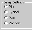
Selecting a time value for delays during simulation
•The delay settings (Section 9.8 Diagram Settings Dialog) determine how delay times will be computed during diagram code generation. This setting determines whether min, typical, max, or random values will be used for the delay time. •The random setting allows a random value to be computed from within the range of the min and max specified for the delay. All delays within a transactor will be randomized when this setting is selected, but delays can be fixed by setting their min and max values equal. •Random values are generated using a uniform probability distribution. For VHDL projects, the default seed for the random number sequence is set in the sequencer process for the project and can be manually overridden by a subsequent call to InitializeUniform(seed1, seed2) by the user. For Verilog, the standard system task, $random, is used to generate random numbers. •The RandomDelays project located in theSynaptiCAD>Examples>TestBencher directory demonstrates how to randomize delays within a range of time or a range of clock cycles, and also how to pass in a delay time to a transaction from an Apply call. |
|
More Information on Delays:
•The Timing Diagram Editor's Manual Chapter 5: Delay, Setup and Hold Parameters has more information on controlling how the delay draws itself and on how to move a delay to different edges after they are drawn. Also, this chapter explains all of the timing analysis features of delays and how they affect the timing diagram. It also covers when an edge is driven by multiple delays ending on the same edge (e.g. this is useful when you want to drive an output signal's edge based on whether an edge transition occurs on one of several input signals). |
•The HDL code generation for all delays, samples, and markers in a timing diagram can be disabled through the TestBencher Diagram Settings dialog. See Section 9.8: Diagram Settings Dialog (TestBencher only) for more information on this feature. |
|