4.2 Setups and Holds |

|

|
|
4.2 Setups and Holds |
|
|
4.2 Setups and Holds |
|
|
|
4.2 Setups and Holds |
|
|
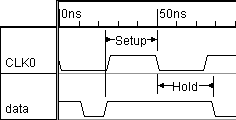
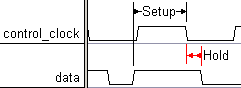
Setups and Holds check timing requirements for a design. Setups are the minimum time necessary that a signal must stay stable before a control signal transition. Holds are the minimum time that a signal must be stable after a control signal transition. Setups and Holds perform one check between two signal transitions. If the setup or hold fails then it outputs a warning in the simulation log file and prints the expected and actual values. If you want to perform a continuous check between two signals you can use the method described in Section 4.3 Creating Continuous Setups and Holds.
Setups and Holds Clock Domains
Setups and Holds are placed in clock domains based on the edge that they point to. Since they cannot be attached to time (such as Samples), they will never be triggered by the unclocked sequence. In the following example there are three different clock domains because the setups and holds point to three different edges:
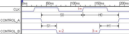
•CLK_pos triggers both S0 and H0 at the second positive edge of CLK. •CONTROL_B_neg triggers S1 at the first negative edge of CONTROL_B. •CONTROL_B_pos triggers H1 at the first positive edge of CONTROL_B. |
To create a setup or hold:
•Press the Setup or Hold button so that right clicks will add that type of parameter. |
|
•Left click on the data signal to select it, then Right click on the control signal to add the parameter. To remember this order, remember that data signals have setup/hold constraints whereas control signals like clocks don't. •If drawn correctly, the arrows will point to the control signal. |
|
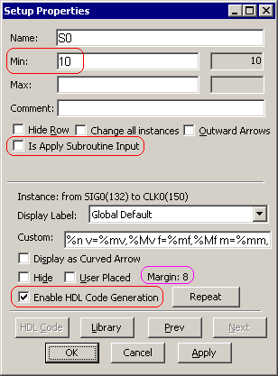
•Double click on the parameter to open the Properties dialog. •Enter a min value, which is is the minimum time that the data signal has to be stable before or after the control edge, and it can be a time value or time formula. The max value is rarely used, but if specified the data signal must occur between the min and max times. See the Timing Diagram Editor's Manual Section 2.5 Time Formulas for Clocks and Parameters for information on the syntax of the formulas. •For TestBencher Pro, the Is Apply Subroutine Input, if checked, generates input ports to the timing transaction that can be used to specify the values to use for the min and max settings of the setup or hold. •The Enable Code Generation enables code generation for this setup or hold. |
|
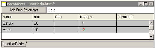
•Margin indicates the amount of safety margin available before the constraint condition is violated.When a constraint is violated, it will turn red in both the Diagram window and the Parameter window. This just shows the margin of the drawn timing diagram; during simulation, margin errors will go to the simulation log file. |
|
•The Outward Arrows checkbox changes the direction that the arrows on the parameter are drawn. This does not affect code generation but it is a popular graphical feature. •Notice that the Setup or Hold also gets added to the Parameter window. |
More Information on Setups and Holds:
•Every setup and hold has two variables, parametername_min and parametername_max, that can be used in other parameters and in user-defined HDL code statements. •The Timing Diagram Editor's Manual Chapter 5: Delay, Setup and Hold Parameters has more information on controlling how the setup and hold parameter draw themselves and on how to move a parameter to different edges after it is drawn. |
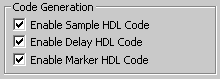
•The HDL code generation for all delays, samples, and markers in a timing diagram can be disabled through the TestBencher Diagram Settings dialog. See Section 9.8: Diagram Settings Dialog (TestBencher Only) for more information on this feature. |
|