|
|||||||||||||||||||||||||||||||||||||||||||||||||||||||||||||||||||||||
|
|
|
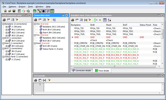
Automatically verifying thousands of connections between PCBsWhen developing large electronic systems consisting of multiple Printed Circuit Boards (PCBs), making sure that each signal is connected to the correct pin of a connector is a cumbersome task. Until now there has not been a way to verify these connections automatically and designers were forced to manually check each connector pin. Using ConnTrace you can process a number of netlists (which may be in different formats), define the connections and trace the signals from board to board.
Intelligent VerificationConnTrace uses rules (based on regular expressions) to match the signal names between PCBs. It allows the tool to validate groups of matches although individual signals can still differ. The rules can be generated automatically and be fine-tuned by the designer. The automated approach will often match 80% to 90% of all connector pins. The flexibility of ConnTrace allows it to be used in any design flow and does not require any design methodology. The rule generator in combination with the sorted problem view allows engineers to validate large systems in a few hours. Once the project and its rules are defined it is a simple task to re-verify the connectors when changed were made to the PCBs. All out-of-date files are processed in one action. Features & Benefits
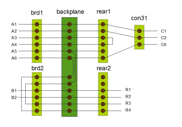
Connectivity TracingThe figure below is an example of the kind of connectivity tracing ConnTrace can perform.
ConnTrace will show that:
Supported PCB Designs SystemsConnTrace supports the majority of Schematic Capture / PCB development systems from the leading vendors Altium, Cadence, Mentor Graphics and Zuken. Different formats may be used within a single project. Most interfaces are based on a netlist generated by the PCB system. If your PCB system is not present please check if it is capable of generating one of the netlists presented below. If you have a netlist format which is currently not supported please contact HDL Works. Adding a new format can often be realized in a short time frame.
Operating Systems
License Configuration
Click here to download ConnTrace EASE, HDL Companion, or IO Checker Would you like a quick walk-through of ConnTrace? Please contact our sales department by phone 540-953-3390 or email [email protected]. |
|
|


