11.2 Import General Instructions |

|

|
|
11.2 Import General Instructions |
|
|
11.2 Import General Instructions |
|
|
|
11.2 Import General Instructions |
|
|
WaveFormer Pro can import waveform data from several simulators and pieces of test equipment. Usually, the Import Waveforms dialog opens and lets you manually choose which signals to load, however once a filter file is created and loaded it automatically determines which signals are loaded. Filter files are created by saving a diagram as a filter file. If this file is then set to be the "filtering file" for the program, any subsequently loaded diagrams will only load the signals contained in the filtering file. In addition, the signal attributes will be set using data from the filter file (e.g. the filter file can contain signal direction, radix, and pin mappings that will be applied to the signals from the files filtered by the filter file). Imports can also be done automatically using the batch mode feature discussed in Section 11.5 Batch Mode.
(Optional) Read Only Mode:
The read only mode may be used to ensure that changes to diagram waveforms can not be made when importing and exporting data. To turn on the read only mode, check the the Options > Read-Only Mode menu.
To import a file for the first time:
•Select the Import/Export > Import Timing Diagram From menu to open a special version of the Open Timing Diagram dialog that remembers the file type of the last file imported. •Select an import format from the Files of type box, enter a file name and press the Open button, if no filter file is specified (see below) then the Import Waveforms dialog will open. |
|
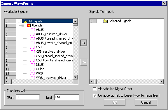
•Select the signals you wish to import, then press the -> button to move them to the import list. •If the Alphabetize Signal Order box is checked, then the signal names will be alphabetized when they are imported, otherwise they will be in the same order as stored in the file. •If the Collapse signals to buses box is checked, then all numbered signals (e.g., bus0, bus1, bus2) to be collapsed to virtual buses (great for logic analyzer inputs). •Also the time frame can be limited to a specific slice, if you enter values in to the Start and End boxes. |
(optional) Create a Filter File after loading a waveform file:
•Save the loaded timing diagram by selecting the File > Save Timing Diagram As... menu, and selecting Waveform Filter (*.tim) from the Save as type box. |
|
•You can also create a filter file by making a new timing diagram then copying and pasting signals into it. |
Using the filter file:
•Choose the Import/Export > Set Filter Diagram File menu to open the Filter Diagram File dialog. •Select the filter file and check the Use Filter box. |
|
•While a filter file is set enabled, it will filter any waveform data that is loaded into WaveFormer, whether it is loaded by opening an existing timing diagram or by importing data from another file format. To disable the filter you only need to uncheck the Use Filter control. •User-defined radices are also saved in the filter files, so you can store your own customized radix for viewing the imported waveform data from a VCD or other waveform source file. |
Import File Formats
•VHDL and Verilog formats: The VCD is the standard output file format for all Verilog simulators and some VHDL simulators. The VCD parser automatically detects Extended VCD and properly handles the signal direction information. The other formats support specific VHDL simulators. |
Verilog Value Change Dump (VCD) SpeedWave VHDL Peak VHDL AWF VHDL Waves Vectors (Aldec) |
•Spice Formats are covered in Section 8.6: Importing Spice waveforms and include SPICE, HSPICE and OmegaSim for both binary and ASCII formats. |
SPICE (csd and tr0) |
•The TDML format is an industry standard XML format called the Timing Diagram Markup Language it is covered in Section 11.3 TDML Management. |
TDML |
•Third party simulators can be imported: •Viewlogic's Viewsim simulator generates Workview WFM files. •Capilano Computing's DesignWorks simulator generates DesignWorks files. •Protel Technology's Advanced PLD simulator generates PLD files. •Sysnopsys's TimeMill generates TimeMill OUT files. |
Workview WFM DesignWorks Protel Advanced PLD Synopsys Time Mill Altera Timing Analyser Output |
•Static Timing Analysis formats: •Altera Timing Analyser files can be read by this program •Xilinx's place and route tool creates *.twx files which contain timing path delays through the FPGA. Timing parameter values can now be imported directly from these files so that you can analyze the timing paths through your post-layout design. |
Altera Timing Analyser Output Xilinx Timing Analyser Xilinx Speed File |
•Test Equipment Formats: •Agilent formats are covered in Section 11.6 Agilent Logic Analyzer - Import. •Tektronix formats covered in Section 11.14 Tektronix Logix Analyzer Import. |
Tektronix/Agilent MSO (csv) Agilent Fast Binary Out (Logic Analyzer)(bin) Agilent Logic Analyzer (hpl) Agilent Wave Logic Analyzer (hwl) Agilent Logic Analyzer/PatGen (CSV) Agilent Infinium Digitizing oscilloscope (txt) Agilent Infinium Raw Data (csv, tsv) Podalyzer Data |
•Spreadsheets can generate waveform data, see Section 11.11: Spreadsheets - Import and Export. |
Test Vector SpreadSheet |
Timing Diagram Formats: •Binary Timing Diagram reads BTIM files that contain all signal and parameters as well as project options in a fast binary file format. This is the default file format for all timing diagrams. |
Timing Diagram - Binary Timing Diagram Timing Designer Free Parm |
•Timing Diagram reads TIM files that contain all signals and parameters as well as project options settings in ASCII based format. This was the standard format used for all timing diagrams before version 8.0 of the SynaptiCAD product line. This format is still support but is slower loading than the btim format. •TimingDesigner accepts TD timing diagram files from Chronology®’s timing diagram editor. •Text Free Parm accepts txt files used for editing libraries saved in the standard spreadsheet compatible file format: comma and tab separated text files that contain a header (first line must be "NAME, MIN, MAX, COMMENT"). This is also compatible with Chronology® library files (formulas are only supported in the td files). •Free Parm reads FP files with just the free parameters information in Timing Project File Format. This is one way to make a library file. |


