11.11 Spreadsheets - Import and Export |

|

|
|
11.11 Spreadsheets - Import and Export |
|
|
11.11 Spreadsheets - Import and Export |
|
|
|
11.11 Spreadsheets - Import and Export |
|
|
The Spreadsheet formats are compatible with spreadsheet programs(like Excel), because the waveform data is stored in a row and column format with the elements in the rows being separated by TAB characters. This format our most generic format and has been adopted by many other companies and products, the most notable is that it is also the format for Tektronix logic analyzers and pattern generators. Also most mathematical analysis products can produce files that are in this format.
Importing and Exporting
•To Import, select the Import/Export > Import Timing Diagram From menu and choose Test Vector SpreadSheet type from the type box. WaveFormer will determine the type of file from the information in the header. |
Test Vector SpreadSheet
|
•To export, select the Import/Export > Export Timing Diagrams As menu and pick one of the test vector spreadsheet types •The test vector spreadsheet outputs a tab-separated row for each change on any signal. The first column shows the time of the change, and there is is one column per signal. •The test vector spreadsheet without timing outputs outputs the same format, except that it does not include the time column. |
Test Vector Spreadsheet Test Vector Spreadsheet without Timing Tektronix Test Vector Spreadsheet clocked
|
•The Tektronix test vector spreadsheet clocked samples the states of the signals on the export clocking signal edge, so it doesn't create a row for each change on any waveform, instead it creates a row for each positive clock edge. |
General instructions for generating a file from a spreadsheet program:
•Inside the spreadsheet program, save your test vector file as a tab delimited table. Sometimes the default setting maybe comma or some other character, so look for a tab type of format. |
Test Vector Spreadsheet Format
The Test Vector Spreadsheet format is organized into different sections, each section describing a different type of signal, such as a clock or bit vector. A single spreadsheet may contain many sections, and each section may contain one or more signals.
The file begins with a free-formatted header which is ignored by the tool, followed by any number of sections and comments. The header can be arbitrarily formatted, since WaveFormer ignores any text until it encounters a section heading.
Sections begin with a section header in the first column. All section headers are single words, first letter capitalized, and wrapped in square brackets (e.g., [Comment]). Any parameters for that section are on the same line as the header, one per cell, as defined by individual section types. The lines following the section header contain information about the section (blank lines are ignored). Any number of sections can be used, in any order. An undefined section header is treated as a comment section and its contents will be ignored. Note that sections and signal names are case sensitive.
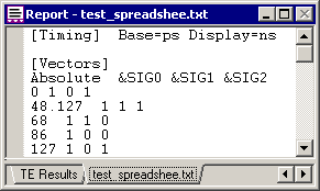
[Timing] Base=time_base Display=time_base
•The base time is the smallest time that is represented by the file. And the Display is the units that time values are written in. The base unit should be at least an order of magnitude smaller than the display unit. Valid units are fs, ps, ns, us, and ms (default is "Base=ps" , "Display=ns"). |
[Clocks]
•The first line after the section header lists the column titles: Name, Period, Offset, Duty, and Invert, in that order. •The remaining lines contain the names of clocks and their attribute values, each in a column. Period, Offset, and Duty are numeric values. Invert is a Boolean value (1 for true, 0 for false). |
[Clocks] Name Period Offset Duty Invert CLK0 100 0 50 0 |
[Vectors] Radix=type_of_radix End=some_integer
•Radix=hex provides a default radix for the file. Should be a valid radix abbreviation (eg, hex, bin, dec). If no default radix is listed, then it is assumed that hex is the default. •End=50 extends signals this far beyond the last event. Defaults to 50 past the last event if not used. •Title Line: The line following the section header must be a title line consisting of Absolute, Relative, all of the signal names to be used in this table, and ended with Comment, each item in its own cell (or separated by TAB characters). Note that a signal probably should not be in two different vector sections since this will cause two signals with the same name to appear in WaveFormer. •Signal Names are defined in the form [@ | & | %]signalname[msb:lsb](radix). •Each signal name starts with an optional special character that determines its direction, when output to certain formats. The @ = input, & = output, and % = in-out. If no character is used, it is considered an output. •The signal name should begin with a letter and not have any spaces or punctuation characters in the name. •After the signal name, is the size of the vector inside of brackets. It is given in [msb:lsb] form (i.e. [7:0] is an eight bit vector). If no size is given, it is assumed to be a single bit vector. Neither of these is considered part of the name. •Next is the radix inside of parenthesis. The words hex, bin, dec, and real are valid entries. If no radix is listed, then the signal will be assumed to be of type of the listed default radix (either the listed one or if not listed than hex). •Each additional line is a list of all of the signal states at given times. The first column, Absolute, gives the time from the beginning of the simulation. Times must be in ascending order. Relative is most often used as the amount of time since the last event (from which absolute is calculated using an Excel formula), but is ignored by WaveFormer. Each signal has a column where its state at that time is stored. Valid states are 1,0,X,Z,H,and L, in upper or lower case. After the last state is an optional comment. Anything after the last signal is ignored, so multi-cell comments are allowed. Any line that does not start with a time is considered a comment, so comments between times are allowed if there is nothing in the first cell. The signals will be drawn to 50 units beyond the last time given, or to the time given by the End parameter. |
[Comment]
•Declares a comment block. Anything inside this section is ignored. |
[End]
•Ends WaveFormer input. When read by WaveFormer Pro, DataSheet Pro or TestBencher Pro, this section header is equivalent to the end of the file. No section beyond this point will be read. |
Example Spreadsheet:
This text is in the Header section. You can put any title you like here.
In the next section the END=50 parameter will cause the signals to be
extended out 50 display time units beyond the last event time.
SIG1 has a bus width of 8 bits.
[Vectors] |
Radix=dec |
End=50 |
|
|
|
|
Absolute |
Relative |
&SIG1[0:7] |
@SIG2 |
&SIG3 |
@SIG4 |
Comment |
0 |
0 |
1 |
0 |
x |
1 |
Start the simulation |
5 |
5 |
2 |
x |
1 |
0 |
|
10 |
5 |
4 |
z |
1 |
0 |
Some data |
15 |
5 |
8 |
z |
0 |
1 |
|
20 |
5 |
16 |
z |
0 |
1 |
|
25 |
5 |
32 |
z |
0 |
0 |
End it |
[Comment]
This section is ignored. Anything can be put in this section.
[Clocks] |
|
|
|
|
|
|
Name |
Period |
Offset |
Duty |
Invert |
|
|
CLK1 |
20 |
5 |
10 |
0 |
|
|
CLK2 |
25 |
10 |
15 |
1 |
|
|
[End] Nothing after this line is read into WaveFormer