WaveFormer Pro can export waveform data into a format that can be read by Pulse Instruments’ pattern generator PI-2005. WaveFormer exports the waveforms as displayed in the timing diagram window. TestBencher supports repeat loop markers that will cause a section of the waveform data to be repeated by the pattern generator.
Each timing diagram should contain one clock. The positive edges of the clock will be used as the sampling points for rest of the waveforms. The period of the clock will be output to the PERIOD statement in the PI-2005 file. By default, WaveFormer will use the first clock in the timing diagram as the sampling signal. If you import waveforms from a simulation file you will need to either add a clock or convert the clocking signal to a SynaptiCAD clock by right clicking on the signal name and choosing Signal <=> Clock from the context menu.
The PI-2005 requires that waveform values be only 0’s and 1’s. So the export script converts non-binary waveform values like tri-state into 1’s during the export. Also the PI-2005 only supports time units of NS, US, and MS for the PERIOD statement. This means that the display time unit for the timing diagram should be set to one these three values.
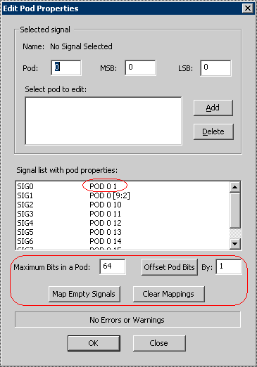
Data is loaded serially one channel at a time into the PI-2005. The signals in the timing diagram are mapped to the channels in the PI-2005 using the Edit Pod Properties dialog. PI-2005 channels start with #1 and use Pod0. You must setup Pod0 so that the maximum pod bits is 64 and the offset is 1.
TestBencher supports repeat-loop markers in the export of PI-2005 data (See Section 5.5: Loop Markers in the TestBencher Pro Manual). Each repeat loop defines a subpattern in PI-2005 file. The smallest subpattern supported by the instrument is 20 clock units long, so each repeat loop should span at least 20 clock pulses. Repeat loops are ignored by WaveFormer Pro.
WaveFormer Pro Instructions:
•Either load or create a timing diagram in the timing diagram editor. •Make sure the timing diagram contains one clock signal, which will be used as the sampling clock. |
•Choose Import/Export > Edit Pods menu to open the Edit Pods dialog. •Set the maximum pod bits to 64 and the offset to 1. •Press the three buttons in this order, Clear Mappings, Map Empty Signals, and Offset Pod Bits. Check to make sure that the first signal mapping is on POD0 and Channel 1. All the other signals should be mapped to POD0. •Press OK to close the dialog. |
|
•Select the Import/Export > Export Timing Diagram As menu option to open a file dialog. •Choose PI-2005 Pattern Generator from the file type drop-down list box. •Type a file name and click the OK button to close the dialog. •The file will be displayed in the Report window. Also any errors or warnings found during export will be displayed in the waveperl.log tab in the Report window. |
PI-2005 Pattern Generator Instructions
The resulting text file is a series of GPIB commands that can be read directly by the PI-2005 pattern generator. Contact Pulse Instruments, [email protected], for details on custom application development and working directly with the instrument. The exported text file can also be imported into the PI-PAT control software.
PI-PAT is the control software and pattern editor for the PI-2005:
1.In the PI-PAT software, create a new PI-2005 document via File > New. 2.Choose File > Import File menu and select the exported text file. 3.Once the pattern file has been imported, PI-PAT may then be used to control the pattern generator and to edit the waveform patterns. |