Import/Export Menu |

|

|
|
Import/Export Menu |
|
|
Import/Export Menu |
|
|
|
Import/Export Menu |
|
|
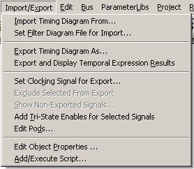
•Import Timing Diagram From reads waveform data from a variety of sources like VHDL/Verilog simulators, logic analyzers, and many other EDA and test equipment sources. It then converts this data into the SynaptiCAD timing diagram format and displays the information in a timing diagram window. See Section 11.2 Import General Instructions. •Set Filter Diagram File for Import specifies a filter file that will limit subsequent imports or timing diagrams opens so that only the signals with matching names will be loaded. A filter file can be used to control what signals get imported from a waveform file (e.g. a VCD file), the order in which they get imported, and the pod/pin mappings of the signal to a pattern generator. See Section 11.2 Import General Instructions. •Export Timing Diagram As opens a file dialog that remembers the last type of file that you exported and allows you to save the timing diagram to different file types. See Section 11.3 Export General Instructions. •Export and Display Temporal Expression Results creates a file callled diagramname_pslresults.txt that contains a list of the times at which temporal expressions match or fail to match. See the Transaction Tracker manual. |
•Set Clocking Signal for Export opens a dialog that lets you specify the clocking signal that is used for clocked export formats like all the pattern generator formats and some third party formats. During export all of the signal values will be sampled on the positive edge of the clock and then written to the file. See Section 11.2 Import General Instructions. •Exclude Selected from Export un-checks the export box in the Signal Properties dialog for all the signals that are currently selected. This will cause the signals to be excluded from export operations. |
|
•Show Non-Exported Signals opens a dialog that displays the names of signals that have been marked for non-export and allows the user to optionally mark the signals for exporting. This menu item is only active when at least one signal has been marked as non-exported. •Add Tri-state Enables for Selected Signals creates a tri-state enable signal for any signal in the timing diagram that has at least one tri-state area in it's waveform. (Used for exporting to pattern generators that do not accept tri-state values on import.) See Section 11.7 Agilent Pattern Generator -Export. •Edit Pods opens a dialog that allows you to map signals to test equipment pods. This is used by most of the pattern generator formats, see Section 11.4 Map Signals to Test Equipment Pins for general information and the special section for your particular piece of equipment. •Edit Object Properties opens a dialog that lets the user attach a strings to the current timing diagram. This is an advanced feature that is used by designers who are writing their own scripts for WaveFormer Pro, DataSheet Pro or TestBencher Pro. See Section C.5 Object Properties. •Add/Execute Script opens a dialog of the same name and allows you to add new perl scripts which will display themselves in the Open, Save As, and Export As dialogs. It also allows you to dynamically execute perl scripts (Chapter C.6 Adding New Scripts). |