11.4 Map Signals to Test Equipment Pins |

|

|
|
11.4 Map Signals to Test Equipment Pins |
|
|
11.4 Map Signals to Test Equipment Pins |
|
|
|
11.4 Map Signals to Test Equipment Pins |
|
|
Normally signal information is exported in the order that it appears in the timing diagram. However, the Pod Properties dialog can define the signal order when exporting to the pattern generator formats. After the Pod Properties have been edited, they will be used instead of the default pod mapping. When the timing diagram is saved, the pod mapping will be saved as well. If any new signals are added to the timing diagram, they will be mapped in the default position. After the pod mapping has been set for a file, any signals that are subsequently deleted will be replaced with internal signals named $$FillerSignal#. The filler signals will be exported to preserve the pod mapping, but they will not be shown on the screen. Redoing the pod mapping will remove the filler signals.
To edit the Pod Properties of a timing diagram:
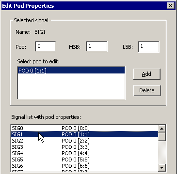
•Select the Import/Export > Edit Pods menu to open the Edit Pod Properties dialog. When the dialog comes up, it will have already mapped the signals to default positions. •Click on a signal in the Signal list with pod properties list box. The signal name and bus size will be displayed in the upper portion of the dialog. The list of pods for that signal will be displayed in the Select Pod to Edit list box. |
|
•To create a pod mapping for a signal, type in a new pod number in the Pod box, set the MSB and LSB, then press the Add button. |
•The Maximum Bits in a Pod box specifies the width of the pod. |
|
•The Offset Pod Bits button will shift the msb/lsb for all signals by the number specified in the By box. |
•The Clear Mappings button clears all pod mappings. |
|
•To map pods to any empty signals: First, select the signal you want to start to the automatic mapping from. Type in the pod, MSB and LSB that you wish to start the mapping at. |
|
•Click the Map Empty Signals button. •This will only map completely empty signals, so if a bus is partially mapped out and the Map Empty Signals button is pressed, the bus will not be changed. |
•Pressing the OK button, makes the dialog check for errors. If errors are found the dialog will stay open and the error will be listed in the error box at the bottom of the dialog. •Signal to pod mappings that contain errors will have an asterisk (*) displayed after their name in the Signal list with pod properties list box. The error message and asterisks will be displayed until the error has been resolved. •If you do not want to fix the errors immediately, then press the CLOSE button and the dialog will close. However, as long as there are pod mapping errors the pattern generator export will not work. |
Pod Mappings Overlap means that there are two or more signals that are mapped to the same pod position. Signal Mappings do not match signal size means that the pod mapping is either too large or too small for a signal. Width is too large for current signal means that the pod you are trying to add is too big for the signal you are editing. Pod number is too large means that the pod number entered in the Pod edit box is greater than the number of pods available to map signals to. Bit Size is too large means that the bit number entered in either the MSB or the LSB edit box is greater than the size of the pods available. |
Generate Tri-state Enable Signals to Turn Pods Off:
Some Pattern Generators support tri-state enable signals that allow an entire pod or group of signals to be alternately disabled and enabled during a test sequence. The tri-state enable signal is high when the associated pod is enabled, and low when the pod is tri-stated. Your particular pattern generator model will determine the rules involving the tri-state signals. To automatically generate a tri-state signal:
•Select the signals that you want to create tri-state enable signals for by clicking on the signal names. •Choose the Import/Export > Add Tri-State Enables for Selected Signals menu option. •Notice that a tri-state enable signal is created for each selected signal that has tri-stated data somewhere on the waveform. •Use the pod-mapping features or arrange the signals so that the tri-state enable signals are exported to the correct pins for your particular pattern generator. Since the tri-state signals usually disable an entire group of pins, make sure that only the signals that you want to be disabled are mapped to those pins. |