5.5 Loop Markers |

|

|
|
5.5 Loop Markers |
|
|
5.5 Loop Markers |
|
|
|
5.5 Loop Markers |
|
|
Loop markers are used to create sections in the transaction that are repeated during simulation. For example, a loop can be used to create a burst read transaction that has to determine, at simulation time, the number of cycles needed to complete the read cycle (see Section 10.3: Burst Mode Transactions). TestBencher and the Reactive Test Bench Option support while loops, for loops, and repeat loops. The exit loop when marker can be used to terminate a loop in the middle of a cycle. Loop Markers can also be used with samples whose Break Loop and Continue Loop actions affect the operation of the loop.
Loop Markers and Clock Domains
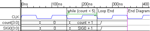
Loop Markers only loop over the clocking domain that they are placed in. The following timing diagram demonstrates how a marker loop might not loop over everything in the diagram. The while loop will loop over the CLK_neg clocking domain since the Begin and End loop markers are attached to falling edges of CLK. The CLK_neg domain also contains the count signal, because that signal has its Clock and Edge properties set to CLK and neg. Each time the loop is executed, the address of the count signal will be incremented. However, SIG0 is outside the CLK_neg clock domain, because its Clock property is set to unclocked. The SIG0+1 equation will be evaluated once and remain static through out the rest of the iterations of the loop.
Triggering Order of Markers and other objects:
Often the signal edges that trigger the beginning and end of loop markers are also triggering other markers and samples. When several graphical elements are triggered off of the same edge then the trigger order determines whether the other graphical elements occur inside or outside of the loop. The order is set by double clicking on the edge and using the Edge Properties dialog (see Section 2.7 Controlling the Triggering Order of Parameters).
Create a Loop using Markers:
The same process must trigger both the beginning and ending loop markers (see Section 2.9 Transaction Clock Domains and Waveform Code Generation). For clocked transactions, this means that the begin and end markers need to be attached to the same edge type of a given signal. For unclocked loops, both markers should be attached to a time. When the timing diagram editor recognizes the beginning and ending of a loop it will draw a green loop line between the markers.
•Add two markers to the timing diagram. Both should be relative to the same signal and edge type, or both should be absolute time markers. •Double-click on the marker on the left to open the Edit Time Marker dialog. Choose one of the loop types to define the beginning of the loop: |
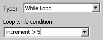
•While Loop marker, when matched with an End Loop marker, will execute continuously over a sequence of test vectors until a defined condition is met. The condition can be any equation in the generation language that evaluates to a TRUE or FALSE at simulation time. |
|
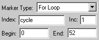
•For loop marker will execute for a specified number of iterations. The Index variable will be automatically created. Each loop the index variable will be incremented by the Inc number. The loop will end when the index becomes greater than the End number. |
|
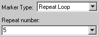
•Repeat Loop marker will execute for a specified number of iterations. |
|
•Press the OK to close the dialog. |
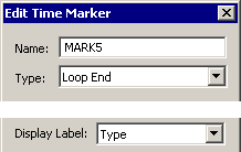
•Double-click on the marker on the right to open the Edit Time Marker dialog. •Choose the Loop End marker type. •If you set the Display Label to Type, then the marker will display "Loop End" instead of the marker name. •Press the OK button to close the dialog. |
|
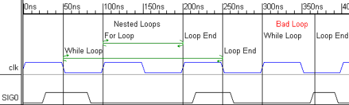
•If the markers are triggered from the same clock domain, then TestBencher will draw a loop line between the markers. If there is no loop line, check the attachments of each marker. In the example below, the bad loop will not work, because the while marker is triggered by the rising edge clk process and the loop end marker is triggered by the unclocked process. |
Break out of a loop early using an Exit Loop When marker:
The Exit Loop When marker will terminate the inner most loop that both graphically surrounds it and that is triggered off of the same clock domain.
•Add a marker to the timing diagram. It should be relative to the same signal and edge type (or to time) as the markers that form the loop to be broken. |
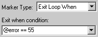
•Double-click on the marker to open the Edit Time Marker dialog. •Choose the Exit Loop When marker type and add a condition on which to exit. The condition can be any equation in the generation language that evaluates to a TRUE or FALSE at simulation time. |
|
Samples can Break Loops or Skip Past Section of the Loop:
•Add a Sample to the timing diagram, as shown in Section 3.1: Adding a Sample. It should be relative to the same signal and edge type (or to a time) as the markers that form the loop. •Double click on the sample to open the Sample Properties dialog. •Press the HDL Code button to open the Code Generation Options dialog. •Define an If Condition as shown in Section 3.2: Sample Checking and Actions. •In the Then Action or Else Action boxes choose one of the following actions: •Break Loop: stops the loop that immediately surrounds the sample. •Continue Loop: returns to the beginning of the loop immediately surrounding the ample, skipping the last part of the loop. |