4.4 Export VHDL and Verilog test benches |

|

|
|
4.4 Export VHDL and Verilog test benches |
|
|
4.4 Export VHDL and Verilog test benches |
|
|
|
4.4 Export VHDL and Verilog test benches |
|
|
SynaptiCAD offers several different levels of test bench generation. This section covers the features in WaveFormer Pro and WaveFormer Lite which generates VHDL and Verilog stimulus models from a single timing diagram. The generated files are normally used with external simulators, and with FPGA tools like Xilinix ISE, Altera Quartus, and Microsemi (Actel) Libero. SynaptiCAD also offers more advanced code generation in the following products:
•Reactive Test Bench Generation Option upgrades WaveFormer, VeriLogger, and BugHunter so that they can generate single diagram test benches that react to the model under test during simulation and produce pass or fail reports. See the Reactive Test Bench manual for more information about this feature.
•TestBencher Pro generates multi-diagram, self-testing, reactive test benches. Perfect for building bus-functional models of microprocessor and bus interfaces. The TestBencher Manual describes this type of generation.
•VeriLogger Pro and BugHunter Pro also generate interactive stimulus test benches (like WaveFormer) except that the testbench is tightly integrated into the simulation debugger and allows for very quick testing of models. Chapter 3: Waveforms and Test Bench Generation of the BugHunter & VeriLogger Manual describes this type of generation.
Import or setup the Signal names and types
In order for the exported testbench model to hook up to your model under test, the signal names (including type, size and direction) must match. You can either have WaveFormer parse and extract this information (auto-extraction requires Reactive Test Bench option) or you can set it manually using the Signal Properties dialog.
Auto-extraction Steps (Reactive Test Bench option required)
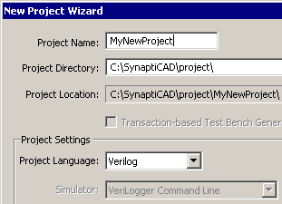
•To extract the information from the models under test, first create a project. •Select the Project > New Project menu to open the New Project Wizard dialog, enter a project name, and set the project language. •Pressing the finish button will cause all the currently open windows to close and a project window to open. |
|
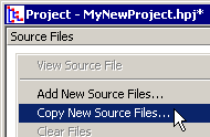
•Next, add the model files to the project, by right clicking in the Project Window and choosing one of the New Source File menus. Copy first copies the model file to the project directory and then adds it to the project. Add just adds the file to the project without moving it. |
|
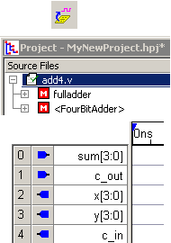
•Press the Extract MUT Ports into diagram button on the main button bar. This will cause WaveFormer to parse the files in the project and populate the project tree so that you can view a hierarchical view of the model under test. •The Extract MUT Ports button will also populate a timing diagram with the ports of the top level module. Output signals drive the model under test and have icons that point to the left. Input signals represent signals with data coming back from the model under test and have icons that point to the right. •You are now ready to draw your testbench waveforms for the signals in the diagram window. |
|
Or manually enter signal type information:
If you add the signals manually, the following settings will need to be set for each signal:
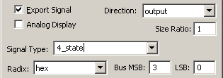
•Double click on a signal's name to open the Signal Properties dialog and edit the name and MSB/LSB. •Check the Export Signal box so that this signal will be included in stimulus generation. |
|
•Use the Direction box to choose output so that the signal will drive the model under test. The other directions are for use with more advanced test bench generation of Reactive Test Bench or TestBencher Pro. •Choose a Signal Type or type in a user-defined type into that box. The standard types are language independent, so the same timing diagram can be used to generate both VHDL and Verilog testbench models. The following are the mappings between the types: |
SynaptiCAD |
Verilog |
VHDL |
4_state |
reg |
std_logic |
4_state_vector |
reg |
std_logic_vector |
bool |
reg |
boolean |
2_state |
reg |
bit |
2_state_vector |
reg |
bit_vector |
byte |
reg |
bit_vector |
int |
integer |
integer |
unsigned_int |
integer |
natural |
real |
real |
real |
fixed_len_string |
reg |
string |
variable_len_string |
|
|
time |
time |
time |
event |
event |
|
std_logic |
|
std_logic |
std_logic_vector |
|
std_logic_vector |
std_ulogic |
|
std_ulogic |
std_ulogic_vector |
|
std_ulogic_vector |
signed_logic |
|
signed |
unsigned_logic |
|
unsigned |
actel_current_delta |
reg |
std_logic |
actel_temperature |
reg |
std_logic |
actel_voltage |
reg |
std_logic |
actel_voltage_common |
reg |
std_logic |
actel_voltage_delta |
reg |
std_logic |
To export a timing diagram:
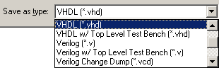
•Select the Import/Export > Export Timing Diagrams As menu option to open a special version of the Save As dialog which remembers the file type of the last file exported. •Select a VHDL or Verilog export format from the Save as type box, enter a file name, and click Save button to generate the file. |
The plain VHDL or Verilog formats generates a stimulus module that can be included into a user-written top level test bench. The Top Level Test Bench types instantiates the model in the Project window and the stimulus model within a top-level model. This top-level module can then be simulated without any additional setup. The VCD format generates a stimulus file that can be read by other EDA tools and test equipment (not a test bench model). |
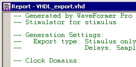
•The generated file will open as a tab in the Report window so you can quickly see how changes in the diagram affect the generated code. |
|
VHDL Library and Use Clause statement support:
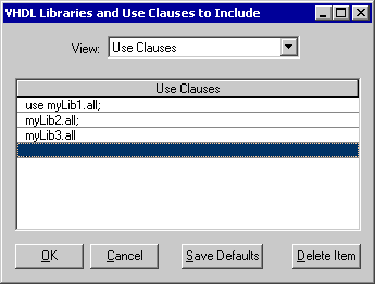
If Libraries or Use Clauses need to be added to the generated model, then specify them in the VHDL Libraries and Use Clauses to Include dialog.
•Choose the Options > VHDL Libraries and Use Clauses menu to open the dialog. Changes made in this dialog will be applied to all diagrams that are exported to VHDL. •From the View control select either Use Clauses or VHDL Libraries and enter the information on to a blank row. |
|
•If the ‘USE’ is omitted from a use clause, or the ‘LIBRARY’ from a library statement, WaveFormer will automatically add ‘USE’ or ‘LIBRARY’ before the clause in the source file for the diagram. If necessary, WaveFormer will also automatically add semicolons to the end of library includes and use clauses |
VHDL User-Defined Types are supported:
•In the Signal Properties dialog, type in the user-defined type into the Signal Type box. |
|
•On the waveform, double click to open the Edit Bus State dialog and enter the state values into the Virtual box. •To make the generated code compilable when you include signals with user-defined types, you will need to add a use clause for the package that defines the type. See the section above this for more information on use clauses. |