4.5 HDL Code Generation Settings |

|

|
|
4.5 HDL Code Generation Settings |
|
|
4.5 HDL Code Generation Settings |
|
|
|
4.5 HDL Code Generation Settings |
|
|
WaveFormer Pro generates a Verilog or VHDL model file from the information in each of the signals. Signals of type Drive generate stimulus vectors, clocks generate clock models, and simulated signals generate Boolean equations, register, or latch circuits. You can view the model file to get an idea of the code that is generated. The Diagram Simulation Preferences dialog has several controls that affect the type of code generated.
Viewing the Generated file:
•Press on the tab named timing_diagram_name.v in the Report window to see the code (or .vhd depending on the selected simulator). If you cannot see the tab, then press the right hand arrow next to the tab bar to see more tabs. If you cannot see the Report window, select the Window > Report menu option to bring it to the top. |
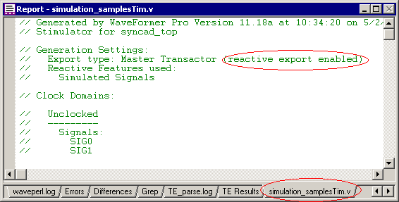
•The top of the file shows which options are enabled for the program. In the above example, the comment indicates that the Reactive Export feature is enabled. The next comments show which signals are in each clocking domain (set by the Clock dropdown in the Signal Properties dialog). A signal's clock domain determines when state changes are output on driven signals (by default, signals are "unclocked" and driven after time delays. |
Changing the type of code generated:
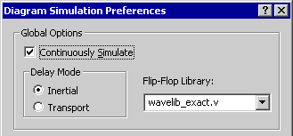
The Diagram Simulation Preferences dialog controls what code is generated for timing diagram simulations.
•Select the Options > Diagram Simulation Preferences menu to open the dialog. |
•The Global Options affects simulation of all timing diagrams in the editor. •The Inertial delay mode causes pulses that are smaller than delay values to disappear. •The Transport delay mode causes all pulses to be transmitted. |
|
•The Flip-Flop Library allows you to specify the parts library that is used for the simulation. This feature is for advanced users who wish to modify the way registers and latches are modeled by the tool. |
•The Continuously Simulate box, if checked, allows the editor to re-simulate each time an edge is moved. This provides the "Interactive" part of the environment. However, you may wish to turn off this feature if the simulations begin to take a long time to run and you do not want to simulate each time you make a minor change. If this box is unchecked, then you can force a simulation by pushing the Simulate Diagram button on the button bar or by pushing the Simulate Once button in the Signal Properties dialog. |
|
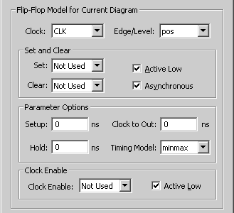
•The Flip-Flop Model for Current Diagram area sets the defaults for newly created signals in the current diagram. These controls work the same as the controls in the Signals Properties dialog and the Advanced Register dialog covered in Section 4.2, except that they affect all new signals instead of just the selected signal. |
|