13.2 SDC from Simulators/Logic Analyzers |

|

|
|
13.2 SDC from Simulators/Logic Analyzers |
|
|
13.2 SDC from Simulators/Logic Analyzers |
|
|
|
13.2 SDC from Simulators/Logic Analyzers |
|
|
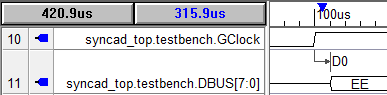
To derive SDC constraints from the timing information contained in simulation or logic analyzer waveform data, just load the waveform file into the timing diagram editor and mark specific signal edges with delay, setup, or hold parameters. Since the timing of the simulated waveforms is exactly the timing for the circuit, you do not need to enter values for the parameters, because you can choose to use "distance variables" rather than "value variables" in the SDC Code generation dialogs.
Load the Simulation File (or any waveform file):
•Choose the Import/Export > Import Timing Diagram From menu to open the Open File dialog. •Pick the type of file and choose your simulation or logic analyzer file format to load into the tool. |
Add a Parameters and enable the SDC Distance Variables:
•Add delay, setup, and hold parameters between signal edges in the waveform file. |
|
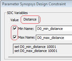
•Double click on the parameter to open the Properties dialog for that type of parameter. •Press the SDC Code button to open the Parameter Synopsys Design Constraint dialog. |
•Press the Distance tab. •Check the Min Name and Max Name check boxes to create the distance variables. These will take the min/max values of the actual distance between the edges. |
|
•In the SDC Commands section, check the Use Min/Max Distance Variables to use the variables you just created. •Also you will need to choose the SDC Command Type to generate. |
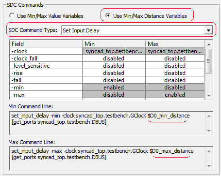
•Notice that the code at the bottom of the dialog is using the distance variables. |