13.1 Generate SDC Code |

|

|
|
13.1 Generate SDC Code |
|
|
13.1 Generate SDC Code |
|
|
|
13.1 Generate SDC Code |
|
|
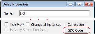
Delays, setups, holds, and clocks can generate SDC code. From inside a timing diagram, double click on an object and then press the SDC Code button to generate the code. Most commands have several options that can be enabled or disabled as needed. Each time a timing diagram file is saved, an associated SDC file of the same name (but with a *.sdc extension) will be generated in the same directory as the timing diagram file.
Check the SDC boxes to generate code:
•Double click on the delay, setup, hold, or clock to open the Properties or Parameters dialog for the object. •Press the SDC Code button to open the Synopsys Design Constraint code generation dialog for the object. |
|
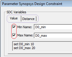
•In the SDC Varibles section of the of the dialog, check the boxes for the variables that will generate code. |
|
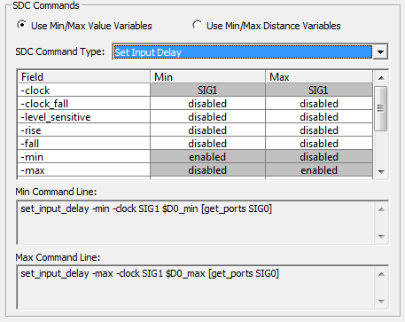
•The bottom of the dialog contains a dropdown list to control the type of SDC command(s) that will be generated for the enabled variables. The grid below the dropdown shows the allowed options for the command type selected. Double clicking on white fields in the grid allows you to enable options and set values for options that accept values. Grey fields are not editable (these are set based on data in the timing diagram object such as the clock or timing parameter that the SDC command is being derived from). You can hover over a field with the mouse to display a tooltip with more information about that specific command option. •The sections below discuss which SDC commands can be generated for each type of timing diagram object. |
Delay Options
Pick one of the delay command types described below to generate SDC code for a delay:
•The Set Input Delay command type generates SDC set_input_delay commands. Use this when a delay parameter represents a timing requirement on inputs coming into the design relative to the design's clock(s). This delay information can be obtained from the data sheets of external hardware developed by third party vendors or from static timing analysis reports for internally developed hardware. |
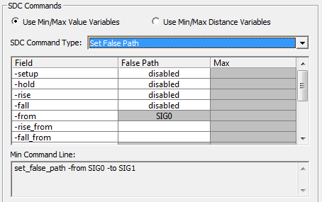
•Use Set False Path command type to generate the SDC set_false_path command. Use this when the delay is on a path that should be ignored by the timing analyzer. |
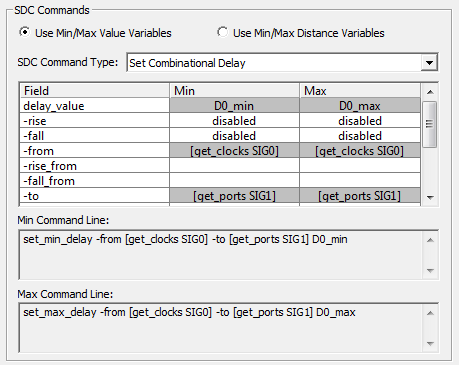
•Use the Set Combinational Delay to specify min/max timing paths on purely combinational paths (no intervening flip-flops) in your design from a design input port to a design output port. You can generate a min only, a max only, or a min/max delay constraint on the combinational path depending on which check boxes you select in the SDC variables section of the dialog. |
Setup and Hold Options
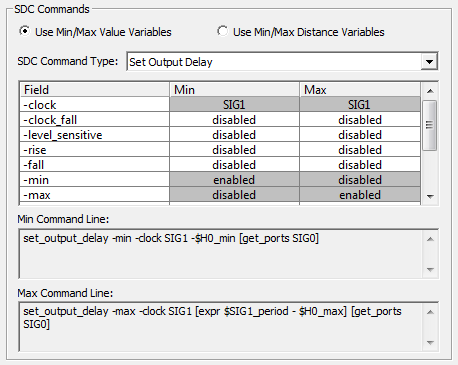
•The Setup parameter generates SDC set_output_delay commands. These commands constrain the timing on design outputs to meet timing requirements imposed on external device inputs being driven by the design. Typically, a setup value will only have a minimum time requirement and this value will generate an SDC command that sets the "-max" output delay. |
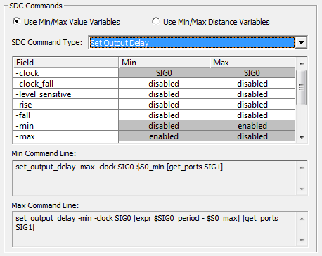
•The Hold parameter generates the SDC set_output_delay command. These commands constrain the timing on design outputs to meet timing requirements imposed on external device inputs being driven by the design. Typically, a hold value will only have a minimum time requirement and this value will generate an SDC command that sets the "-min" output delay. Due to SDC conventions, the delay time for the -min output delay command will be the negated value of the hold's min time. |
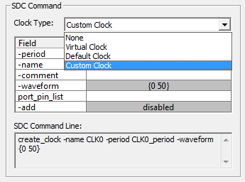
Clock Options
A standard clock in the timing diagram will generate SDC create_clock commands. Derived clocks (clocks that are based on a reference clock) will generate SDC create_generated_clock commands.
For both types of clocks, you must specify the clock type: default, custom, or virtual. Default and custom clocks are used to constrain internal timing paths in your design, whereas virtual clocks are often useful for constraining timing on design IO pins. Default clocks will tie the clock to any pins that match the name of the clock signal in the timing diagram. Custom clocks allow you to enter a port_pin_list that lists the clock pins in your design that should be attached to the command. Virtual clocks represent external clocks that don't directly attach to pins in your design.