13.3 Linking and Editing SDC files |

|

|
|
13.3 Linking and Editing SDC files |
|
|
13.3 Linking and Editing SDC files |
|
|
|
13.3 Linking and Editing SDC files |
|
|
For the SynaptiCAD products that contain a project window, multiple SDC files can be linked together and easily viewed and edited. WaveFormer with Reactive Testbench option, DataSheet Pro, TestBencher Pro, and BugHunter (or VeriLogger Extreme) all contain the project window. Timing Diagrammer and WaveFormer Pro do not have the project window.
Creating a Project and Add the Timing Diagram to it:
For most of the products listed, you may have already created a project in which case you can skip this review.
•Choose the Project > New Project menu option to create a project and open the Project window. •Inside a timing diagram, right click in the signal name pane and choose Add Diagram to the Project from the context menu to add the diagram to the Transaction Diagrams folder. |
SDC Project Window Navigation and Editing:
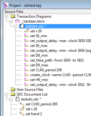
Every timing diagram BTIM file has an SDC file of the same name that contains the generated SDC code for the timing diagram. The SDC file will only exist if you enabled SDC code generation as described in the previous section.
•In the Project window, under the Transaction Diagrams folder, you will find the timing diagrams and their associated SDC files. •Opening an SDC file node will display the commands in the file. •Double clicking on a command will open the SDC file in an editor window and put the cursor on the selected line of code. You can then edit the command directly. •Selecting a line of code and pressing the Delete key will remove the command from the file and make the appropriate changes to the timing diagram. |
|
Link by Dragging and Dropping
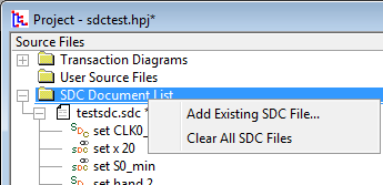
Timing Diagrams can also access other SDC files by listing them in the SDC Document List folder and by dragging commands back and forth between the files.
•Under the SDC Document List folder, right click and choose Add Existing SDC File from the context menu. •To Link SDC commands, drag and drop SDC commands to and from the listed SDC files and the timing diagram SDC file. |
|
•Notice that icons for the SDC code lines change depending on what is driving them. The plain SDC icon means that is driven only by the SDC file containing the line. A little waveform means that the command is driven by a timing diagram. And the chain link symbol means that it is linked so that changes to either location will effect this line of code. If any linked command is driven by a timing diagram object, this will control the values of all linked commands (only one command in a link set can be driven by a timing diagram object). |