2.3 Grid Lines on Clocks and Signals |

|

|
|
2.3 Grid Lines on Clocks and Signals |
|
|
2.3 Grid Lines on Clocks and Signals |
|
|
|
2.3 Grid Lines on Clocks and Signals |
|
|
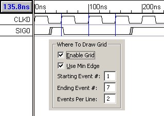
Grid lines are vertical lines drawn from the edges of a clock or on any signal.
To draw a grid lines:
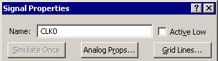
•Double-click on the clock name to open the Signal Properties dialog, and press the Grid Lines button in the top right of the dialog. This opens the Grid Options dialog. |
|
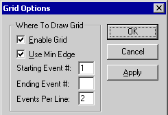
•Check the Enable Grid checkbox. This enables the rest of the grid options. If you later decide to turn off the grid then uncheck this check box. •Fill in the rest of the controls to design a grid pattern. Use the Apply button to test your grid settings. |
|
Where to Draw Grid Section:
•The Use min Edge check box determines if grid lines are drawn from the minimum or maximum edge of a clock transition. •The Starting Event # is the event number where the first grid line is to be drawn. The first event in the clock is the 0 event. •The Ending Event # is the event number where the last grid line is to be drawn. If blank, the will draw on all the clock edges. •The Events per Line edit box determines how many clock transitions occur before another grid line is drawn. A "1" draws a grid line on every transition, and "2" skips one transition between grid lines, etc. |
|
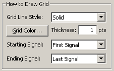
How to Draw Grid Section:
•The Grid Line Style determines what kind of grid line is drawn. All the standard Windows line styles are available: solid, dash, dot, dash-dot, and dash-dot-dot. •The Grid Color button allows the user to set the color of the grid lines and Thickness sets the width of the line. •The Starting Signal and Ending Signal determine the length of the grid lines. The default values cause the grid lines to be drawn from the top of the diagram to the bottom. |
|
Hidden Signals and Text Objects:
Normally, hiding a signal will also hide the grid lines and text attached to the signal. However, sometimes it may convenient to use a signal just for holding grid lines (or text), but otherwise that signal is unrelated to your circuit design and does not need to be displayed. The checking View > Show Hidden Text menu, then hiding the documentation signal will allow the grid lines to continue to be displayed even though the signal is hidden.