2.4 Modeling Clock Skew with Delay Correlation |

|

|
|
2.4 Modeling Clock Skew with Delay Correlation |
|
|
2.4 Modeling Clock Skew with Delay Correlation |
|
|
|
2.4 Modeling Clock Skew with Delay Correlation |
|
|
Datasheets for clock tree buffer ICs often include a timing skew parameter that can be used to compute the delay correlation between the buffer gates inside the IC. To take advantage of the skew information, you must first specify a buffer gate delay for each of the clocks being buffered by the clock tree. Next, you will compute a delay correlation from the skew value. Finally, you can create a correlation group with the calculated delay correlation value that contains the clock buffer delays. This delay correlation group will automatically account for the clock skew in all the timing calculations related to the clocks.
1) Enter the buffer delays into each buffered clock
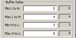
•For each clock, double click on the waveform to open the Edit Clock Parameters dialog and enter the buffer delays in the Buffer Delay section of the dialog. Close the dialog when you are done with all the clocks. |
|
This causes the program to automatically generate two delay parameters (one for the rising edge delay and one for the falling edge delay) for each clock. These are the parameters that you will add to the correlation group in step 3.
2) Compute the delay correlation using the skew value for the clock tree buffer:
•First, use the min and max buffer delays from your data sheets to calculate the buffer uncertainty. |
BufferUncertainty = MaxBufferDelay - MinBufferDelay |
•Then use the skew value from the data sheet to calculate the delay correlation. |
DelayCorrelation% = (1 - (Skew / BufferUncertainty)) * 100 |
3) Create the Correlation group for the clock buffer delays
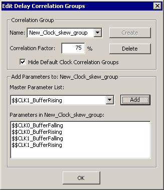
•Double click on one of the clock waveforms to open the Edit Clock Parameters dialog and press the Correlation button to open the Edit Delay Correlation Groups dialog. |
|
•To create a new group, type in a name and press the Create button. •Enter the DelayCorrelation% value into the Correlation edit box. •Add the two buffer delays for each buffered clock to the correlation group by selecting them from Master Parameter List and pressing the Add button. Each clock will have two delays named $$ClockName_BufferRising and $$ClockName_BufferFalling. •Note that the finished correlation group should have at least 4 delays (2 for each clock being correlated). There will be two more delays for each additional buffered clock. |
|
Example of how to calculate delay correlation using skew
Assume you have a datasheet for three clock buffers where the buffers have a 2-6 ns propagation delay, with a skew of 1 ns between the buffers. Enter the 2-6 ns delay into the Buffer Delay section of the Edit Clock Parameters dialog of all three clocks being buffered. Next, computing the delay correlation for the buffers, we get:
•BufferUncertainty = 6ns - 2ns = 4ns
•DelayCorrelation% = (1 - (1ns / 4ns)) * 100 = 75%
Create a correlation group with a 75% correlation factor and add the buffer delays to the group (3 clocks x 2 buffer delays per clock = 6 delays to add to group). If the clock buffers were perfectly correlated (100% correlation), the skew would be 0ns. If the clock buffers were not correlated at all (0% correlation), the skew would be 4ns. This large skew (no correlation) is the default timing value that is used when no correlation groups are used.
Side Note: For each clock, two correlation groups are also created which automatically correlate the buffer delays for that clock signal. These groups share the same name as the clock buffer delays (e.g. if the clock buffer delay is called $$CLK0_BufferRising, a correlation group called $$CLK0_BufferRising is also created). These special correlation groups allow the software to automatically ignore uncertainty between the edges of a specific clock that is caused by the clock's buffering. Generally these special correlation groups can be left "as-is".