9.3 Filtering Unimportant Differences |

|

|
|
9.3 Filtering Unimportant Differences |
|
|
9.3 Filtering Unimportant Differences |
|
|
|
9.3 Filtering Unimportant Differences |
|
|
Waveform comparison can ignore glitches (zero time changes) in a signal can by checking the Ignore Glitches option. The tolerance, clock, and don't care regions allow the compare feature to ignore other differences that do not matter. The tolerance settings specify regions around the reference signal in which to ignore any differences. The clocked feature will cause the compare to only be performed in the specified region around the clock edges. Don't care regions can also be placed on the reference signal, to remove those regions from the compare calculation.
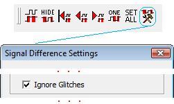
Filtering Glitches (zero time differences between signals)
•Press the Signal Difference Settings button to open the Signal Difference Settings dialog. Check the Ignore Glitches button to filter out zero time differences between signals. |
|
Open the Signal Properties dialog to set Tolerance or specify a clocking signal:
•To modify the tolerance for all the compare signals press the Set All button, to select the compare signals and open the Signal Properties dialog in group editing mode. |
|
•To modify the tolerance for one compare signal, just double click on the signal's name to open the Signal Properties dialog in individual mode. |
Set the Tolerance:
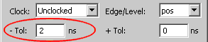
By default, all compare signals have a tolerance of +/- zero, so that any difference between the signals will be displayed. However, positive and negative tolerances can be specified so that the compare will ignore small differences within the range of tolerance values.
•For unclocked signals, the -Tol and +Tol boxes specify the region to IGNORE differences before and after the edge on the reference signal. |
|
Setup a Clocking Signal:
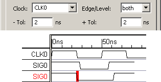
Clocked comparisons provide the ability to compare signals on clocked edges. This is useful if you want to verify that signal values match after state transitions in a clocked system, but are not concerned with the signal values between those transitions (e.g. to ignore "glitch" differences).
•Select the clocking signal from the Clock box and indicate which edges of the clock signal will be used for the time of comparison using the Edge/Level box. •For clocked signals, the -Tol and +Tol boxes specify the region in which to MARK the differences before and after the clock edge. (This is the opposite meaning from the unclocked signal). |
|
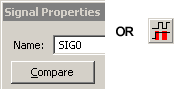
Force a compare using the Signal Properties dialog
•Press the Compare button in the Signal Properties dialog, or press the Compare All Compare Signals button to force the a compare. |
|
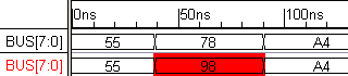
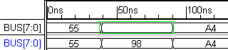
Setting Don't Care Regions
Sometimes you may not want to compare certain regions in time on a particular signal. One case would be on a bus signal where the actual data did not matter. If you want the compare function to skip a particular section, then just turn the waveform into a blank valid region on the reference signal.
•Locate the waveform section on the reference signal (not the compare signal). |
|
•If the segment is a valid segment with a value in it, then double click on the segment to open the Edit Bus State dialog and erase the value in the Virtual box. |
|
•If the segment is a graphical state other than valid, then highlight the section by clicking on it and then press the VAL waveform button to change the graphical state to valid. |
•Rerun the compare function using the Compare All Compare Signals button. |
|
If you are creating a lot of don't care regions, then save the data in your reference file before you load the first compare file. That way each time that you bring in a new simulation run or logic analyzer capture, the reference file will already be formatted properly.