9.4 Transaction Tracker |

|

|
|
9.4 Transaction Tracker |
|
|
9.4 Transaction Tracker |
|
|
|
9.4 Transaction Tracker |
|
|
The Transaction Tracker Option displays areas in a waveform file that match a transaction pattern defined as a PSL (Sugar) equation.
Vocabulary
•Temporal assertion: an equation-based description of a "transaction pattern". •Transaction record: an attempted match of a temporal assertion at some particular time. |
Using Transaction Tracker
Generally the first step when using Transaction Tracker is to load a waveform file containing simulation results or data captured by a logic analyzer. After loading a waveform file, you can add new signals and define transaction patterns to analyze the waveform data. The transaction patterns are written as temporal assertions in the industry-standard PSL/Sugar assertion language and a clocking signal is specified that indicates when the assertion should be evaluated.
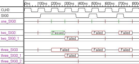
Once the temporal assertion is simulated, the associated signal will display the fails and passes of the pattern as transaction records. A new match attempt will be made each clock cycle and several match attempts can proceed in parallel. If a transaction fully matches the pattern, the transaction record will be displayed in green. If at some point a transaction fails to match the entire pattern, its transaction record will terminate at that point and display in red as a failed match.
A match is attempted for a transaction pattern each new clock cycle. If the pattern does not begin to match during a cycle, a red spike will be created. If the pattern is fully matched during a single cycle, you will see a green spike at this cycle. If a pattern takes several cycles to match or fail, the transaction record will display as a green or red valid segment.
Most transaction patterns require several clock cycles to match, so it is possible that a pattern may generate several transaction records that overlap in time. Transaction Tracker will create additional "overflow signals" when these overlaps occur, so that the original signal's display does not get too cluttered. The later overlapping records will be displayed on these overflow signals (the time used to determine the placement of the transaction records is the "end" of the transaction, not the beginning).
To create an assertion, perform the following steps:
•Select File > Load Timing Diagram to load a file with waveform data to analyze. The file can be a timing diagram, a VCD file, or any other waveform file supported by SynaptiCAD. •Create a new signal by clicking on the Signal button, then double click on the signal name to open the Signal Properties dialog. |
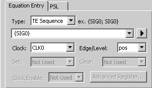
•In the Equation Entry tab, set the Type drop-down to either Temporal Sequence or Temporal Property. •Type a temporal assertion (e.g. {SIG0}) into the edit box below the equation type drop-down. •From the Clock drop-down, choose a clock signal for the assertion and set the Edge Level setting to either pos for rising edge sampling or neg for falling edge sampling. |
|
•Click on the Simulate radio button to activate the assertion for simulation. |
Frequent Usage Tip:
•Use the File > Merge Timing Diagram to merge in a file containing your transaction tracker signals. After you analyze a simulation file for the first time, save off the transaction signals to a separate diagram via copy and paste, so that you do not have to re-create your transaction signals containing the temporal assertions when you want to repeat the analysis on a different set of waveform data. |
Syntax for Transaction Tracker:
Transaction Tracker supports the "simple subset" of PSL version 1.1. The simple subset is the part of PSL supportable by simulators; the remaining PSL functionality is primarily intended for formal verification tools. To get a quick introduction, we recommend you start by launching Transaction Tracker (or other SynaptiCAD tool with the Tracker option), loading the psltutorial1.btim timing diagram file located in C:\SynaptiCAD\Examples\sugar, and reading the associated Transaction Tracker Tutorial in the online help. A valid license is required to perform this tutorial.
After reading the introductory tutorial above, we also recommend that you read the general PSL Sugar tutorial found in c:\SynaptiCAD\Examples\sugar\sugar_tutorial.pdf.
For a complete copy of the PSL 1.1 Language Reference Manual (LRM), please visit http://www.haifa.il.ibm.com/projects/verification/sugar/index.html. This site is maintained by the creators of the Sugar assertion language, and it also contains a number of other documents discussing various aspects of PSL/Sugar that may be of interest.
Temporal Assertion Error Reporting Procedence
1) When defining an assertion using the Signal Properties dialog, the dialog checks if a clock has been specified in the Clock drop down and generates an error message box if not.
2) Next, the PSL assertion parser checks for illegal PSL syntax. PSL syntax errors are reported in the TE_parse.log tab in the Report window. Note: the parser does NOT verify that the signal names in the assertion are valid signals, as the signals will generally be declared in the attached verilog code (this check is made in the next step below).
3) If the above checks succeed, the Verilog compiler will execute and report any references to unknown identifiers in PSL assertions (because an associated verilog file is generated for the PSL file). These will be reported as an "undeclared signal error in diagram_name_vunit.v" typically. Errors detected by the Verilog compiler will be reported in the Errors tab of the Report window and in the simulation.log file.
Files Generated by Transaction Tracker
During a transaction tracker simulation run, the following files will be generated, given an input diagram of diagram_name.btim:
•diagram_name_vunit.psl: PSL file containing PSL code for the assertions in the btim file. The assertions are grouped into vunits that are clocked off the same clock edge. •diagram_name_vunit.v: Verilog file that connects PSL equations to the HDL source code. •diagram_nameTim.v: Verilog file that contains stimulus signals and HDL simulated signals. •TE_parse.log: Error messages generated during parse of PSL assertions. •Simulation.log: Error messages generated during compile of HDL code and log messages generated during simulation run. •diagram_name_pslresults.txt: Text file containing the transaction records of all the PSL assertions, in time order. |
This file is created by selecting the menu option Import/Export > Export and Display Temporal Expression Results. The same results will also be displayed in the TE Results tab in the Report window.
Notes and Limitations
•TE signals can reference TE signals and Boolean Equations, but Boolean equations cannot reference TE signals. •Transaction Tracker supports only the vunit and assert commands from the verification layer. The modeling layer is not applicable to Transaction Tracker. •The following PSL built-in functions are not yet supported: isunknown, countones, onehot, onehot0, next, prev, stable, and the union operator. •PSL endpoints are not yet supported. |