2.1 Adding Clocks |

|

|
|
2.1 Adding Clocks |
|
|
2.1 Adding Clocks |
|
|
|
2.1 Adding Clocks |
|
|
Clocks can be created using the Add Clock button or converted from a signal through the right click menu. Clocks can be selected, moved, deleted and hidden just like regular signals. However, clock edges are fixed and cannot be pushed by a delay parameter or dragged using the left mouse button.
Add a new clock:
•Press the Add Clock button, to create a new clock and open the Edit Clock Properties dialog. |
|
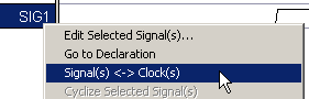
•Or, if importing from a VCD or logic analyzer the clock data will import into regular signal and will need to be converted into a clock. Right click on a signal name and choose Signal(s) <-> Clock(s) option from the menu. The editor will attempt to determine the parameters of the clock (period, offset, duty cycle, etc.) from the signal waveform; if editor cannot determine these parameters, the clock will have the default parameters. |
|
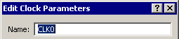
Open the Edit Clock Parameters dialog:
Most of a clock's parameters are edited using the Edit Clock Parameters dialog. This is a fully interactive dialog that changes the clock as soon as you change a clock attribute, so you can immediately see the impact on your design.
•Double-click the waveform of the clock to open the Edit Clock Parameters dialog. •Or, double click on the clock name and press the Clock Properties button. |
|
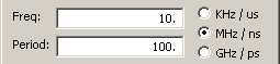
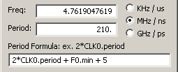
Define Clock Period or Frequency (three ways):
1) By fixed time or frequency:
•The clock rate can be entered as either a frequency or a period (the other will adjust itself). These must be positive real numbers whose units are controlled by the radio buttons to the right of the edit boxes. If you encounter clock frequency rounding errors, lower the base time unit (see 1.10 Base and Display Time Units). |
|
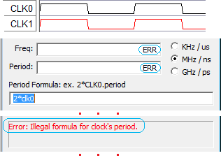
2) By a time formula based on other clocks and parameters. This is particularly useful for describing circuits in which the clock frequency and delay values change depending on the speed grade of the part being used or for phase-locked loop (PLL) frequency multiplier circuits. By storing a clock frequency in a parameter, and referencing that parameter in the frequency box of the clock, the entire diagram can be changed by loading in a different parameter library for each speed grade.
•When a Period formula is entered, the period and frequency boxes will update to show the calculated times. See Section 2.5: Time Formulas for all of the rules for formulas. |
|
•Clocks can reference another clock's period, duty, offset, and rising (jrise) and falling (jfall) edge jitter, and the four buffer delays (minLH, maxLH, minHL, maxHL). |
clockname.period clockname.duty clockname.minLH |
•At the very bottom of the dialog there is a status box that indicates whether or not a clock has an error. In the case shown, the clock's period formula is wrong because clock names are case-sensitive. The correct formula for CLK1 should be 2*CLK0. |
|
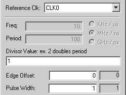
3) By a Reference Clock which tightly relates two clocks and is the most accurate way to model a clock divider implemented with digital logic. This also correctly models delay correlation effects between the reference clock and the sub-clock.
•When you choose a reference clock, the period, offset, and duty cycle edit boxes are replaced by three new edit boxes called Divisor, Edge Offset, and Pulse Width which are all tightly related to the reference clock. •The Divisor affects the period of the new clock. A divisor of 2 makes the new clock have twice the period of the reference clock (half the frequency, acts as a clock divider circuit). A divisor of 0.5 divides the period by 2 (acts a frequency multiplier circuit, e.g. phase-locked loop circuit). |
|
•Edge Offset is the number of edges of the reference clock that the new clock waits until starting. A value of 0 starts the new clock on the rising edge of the reference clock. A value of 1 starts the new clock on the first falling edge of the reference clock. (Assuming the reference clock is not inverted). This only has meaning when frequency is being divided; multiplied clocks ignore this value. This box can accept a time formula. •Pulse Width is the number of edges of the reference clock that determine the width of the new clock. To get a 50% duty cycle the Pulse Width must equal the Divisor. For example a clock with a divisor of 2, has a period equal to 2 periods of the reference clock. If you count the edges on the reference clock (0,1,2) will bring you to the beginning of the second period of the reference clock. So a pulse width of 2 will give you a 50% duty cycle. This only has meaning when frequency is being divided, multiplied clocks ignore this value. |
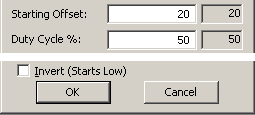
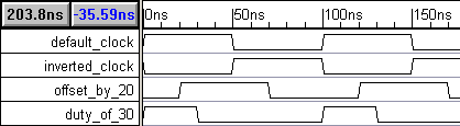
Offset, Duty Cycle, and Invert
•The first default clock transition is a rising edge at time zero. The offset value shifts the clock transitions by an amount of time.This can be a formula. •Duty cycle is the percentage time that a clock is high during a given period. This can be a formula. |
|
•Checking the invert box reverses the clock so that it is low at time zero (unless there is a starting offset). |
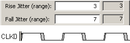
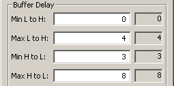
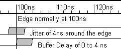
Edge Jitter and Buffer Delays
•Edge Jitter adds uncertainty around the clock edge, and is used to model PLL jitter or frequency fluctuations in a crystal oscillator. |
|
•Buffer delays add uncertainty after the calculated edge time, and models the delay of a clock passing through a buffer. Clock skew can be model using the buffer delays and the delay correlation boxes (see Section 2.4: Modeling Clock Skew). |
|
•The Jitter and Buffer boxes can also accept time formulas. |
|
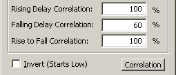
Buffer Delays for clocks are automatically correlated:
Normally, buffer delays are 100% correlated, because the uncertainty from the buffer doesn't add "edge-to-edge" uncertainty to the clock's edges. In other words, the same amount of uncertainty will exist between all the edges of the clock, so it can be ignored for "edge-to-edge" related measurements and for delay chains that start on the clock's edges.
•Although rarely necessary, you can modify the delay correlations directly in the Edit Clock Parameters dialog. |
|
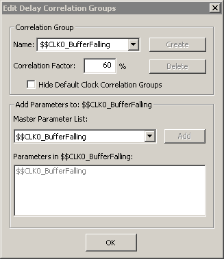
•They can also be edited by pressing the Correlation button to open the Edit Delay Correlation Groups dialog. •Uncheck the Hide Default Clock Correlation Groups box. •Each clock will have three default correlation groups: $$cname_BufferRising $$cname_BufferFalling $$cname_BufferRisingFalling •Each default group will have one delay by the same name. In the diagram window, each buffered clock edge is affected by the corresponding delay. |
|
Display tricks for Clocks:
•To make just a clock have straight edges, while all of the rest of the signals have slanted edges, double click on the clock name to open the Signal Properties dialog, the press the Analog Props button to open the Analog Properties dialog, then check the use straight edges control. To make all of the signals have straight edges see Section 1.4 Display Settings for Signals. •To add virtual state information to segments on a Clock, press the Hex button and then double-click on the middle of the segment to open the Edit Bust State dialog. If the Hex button is not pressed, the double-click will open a different dialog to allow editing of the clock. •To add little arrows on the edges of clocks, double click on the clock name to open the Signal Properties dialog and check the Falling Edge Sensitive or Rising Edge Sensitive boxes. |