8.2 Project Simulation Properties Dialog |

|

|
|
8.2 Project Simulation Properties Dialog |
|
|
8.2 Project Simulation Properties Dialog |
|
|
|
8.2 Project Simulation Properties Dialog |
|
|
The Project Simulation Properties dialog controls how a project is compiled and run, and determines the simulator run time options and which simulator to use for projects and diagrams. If you are moving projects back and forth between different machines and simulators, you may wish to create aconfiguration template for each machine. Also you may wish to have different configuration for different debug and release setups. The basic operation of this dialog is covered in Step 7: Setup External Simulators. This section defines each of the controls in more detail .
To open the Project Simulation Properties dialog:
•Press the Project Simulation Properties button or choose the Project > Project Simulation Properties menu to open the dialog. |
|
Global versus Project Settings
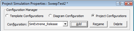
•Select Template Configurations to edit the default settings that are used by new projects. These are stored in the INI file each time the program is closed. The Restore Default Templates button (at the bottom of the dialog) is used to reset the INI file to the factory default settings for this dialog. •Select Diagram Configuration to edit the options for how transactions are simulated (simulated signals in a Diagram window). These are stored in the INI file. •Select Project Configurations to edit the project settings for the current project. These settings are stored in the Project HPJ file when you save the project. |
Configurations:
If you are moving projects to different machines or if you want to have different project settings for debugging and releasing a project you may want to create a new configuration to store the different settings. You can also create different configurations for different simulators which need different command line options. Configurations are also useful if you have projects containing source files in multiple languages and you occasionally only want to compile files of a particular language type (for example, when you're translating from VHDL to Verilog and only want to compile the translated files).
The Debug Configuration holds the default settings. If you need to create a new configuration:
•Press the Add button to open the Add New Configuration dialog and you specify a name and the default configuration to copy settings from. •Rename button lets you change the name of the current configuration. •Delete removes the current configuration. •Use the Configurations drop-down to choose which configuration is currently active (e.g. which settings will be used for compiling and running simulations). |
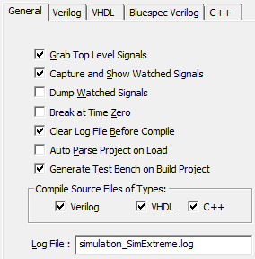
The General tab contains simulation options that are standard across all of the simulators.
•Grab Top Level Signals turns on the automatic monitoring of ports or internal signals in the top-level module. •Capture and Show Watched Signals enables the display of waveform results from a simulation run. •Dump Watched Signals generates a dump file for any watched signals in the diagram. The generated file named diagramName.VCD. |
|
•Break at Time Zero is the equivalent of setting a breakpoint at time zero. This starts the simulator and allows you to enter commands into the console window that will be executed during simulation. •Clear Log File Before Compile clears the simulation log just prior to a new compilation being performed. Note that in this dialog you can also change the name of this log (see Logfile below). •When the Auto Parse Project on Load box is checked, user source files are automatically parsed and built when the project is loaded. The top-level module is the first module that is not included by another for Verilog; it is the first entity/architecture pair parsed for VHDL. This is mainly used by Actel Libero customers with WaveFormer Lite. •Generate Test Bench on Build Project automatically updates the test bench for changes to timing diagrams. Turn this off if you want to temporarily change some of the generated source code manually or to avoid updating the test bench on diagram changes. •Compile Source Files of Type section specifies which kind of files to compile. This is especially important for V2V translation projects, and projects with mixed language code. Consider using this along with the above Configurations setting, by having a VHDL configuration and a Verilog configuration for doing different simulations. •The Log File specifies the name of the log file that receives all the simulation results and information. By default TestBencher uses simulation.log. |
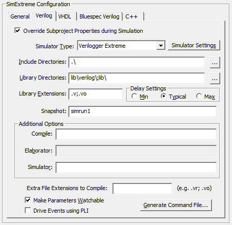
The Verilog tab specifies the simulator and simulation options used for Verilog projects.
•Simulator Type determines the simulation tool used when compiling source files for a given language. •Simulator Settings button opens the Simulator / Compiler Settings dialog where you can edit the path to the simulation tool. |
|
•Include Directories specifies the directories where TestBencher searches for included files. The following is a Windows example (Unix users should use the / slashes): C:\design\project;c:\design\library •Library Directories lists the path and directories where the program searches for library files. TestBencher will try to match any undefined modules with the names of the files that have one of the file extensions listed in the Lib Extensions edit box. The simulator does not look inside a file unless the undefined module name exactly matches a file name. The simulator does not look at any files unless there are file extensions listed in the Lib Extensions edit box. The following is a Windows example (Unix users should use the / slashes): C:\design\project;c:\design\library •Lib Extensions specifies the file name extension used when searching for library files in the library directory. Each library extension should begin with the period character followed by the extension name. Use a semicolon to separate multiple file extensions. .v;.vo •The Delay Settings radio buttons determine which delay value is used in min:typ:max expressions. These settings are output as either the +maxdelays, +mindelays, or +typdelays command line simulator option. •The Snapshot box accepts a text string that will become the name of the executable that is built (overriding the normal name of the simulation build). •Compile, Elaborator, and Simulator option edit boxes allow you to set additional command line options that will be passed to the tool when it is run. Most simulators do not support all three phases of command line options. •The Make Parameters Watchable determines whether or not parameters will be included with the automatic monitoring of ports and internal signals in the top-level module. •The Drive Events using PLI checkbox changes the way stimulus from the StimulusAndResults diagram is sent to the simulator. By default, stimulus waveforms cause Verilog stimulus code to be compiled into the simulation (see Section 3.2: Drawing Waveforms for Stimulus Generation). But when this option is checked, stimulus is directly injected into the simulation at runtime via a PLI application that reads from the btim timing diagram file. This allows you to change the stimulus by editing the btim file without requiring a recompile of your simulation. The disadvantage of this approach is that you cannot single step through the stimulus, since it's injected via PLI. •The Extra File Extensions to Compile adds more types of files that will be treated as Verilog files. •When the Generate Command File button is pushed, the text contained in the Simulator Options edit box along with the list of Verilog files specified in the Project window are written to a Command File. This file can then be used with the Command Line version of your simulator to run a simulation without the TestBencher GUI. |
The VHDL tab contains the simulation options and simulator used for VHDL projects.
•Simulator Type determines the simulator. |
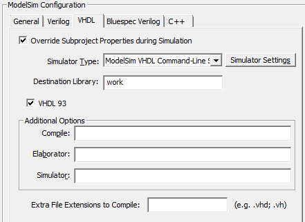
•The Simulator Settings button opens the Simulator / Compiler Settings dialog where you can edit the simulator paths. •The Override Subproject Properties during Simulation makes the subprojects use the properties of the top-level project during simulation (and ignore their own private properties). This only affects TestBencher projects that use hierarchical sub-projects. •The Destination Library controls the logical library that sources files will be compiled into when a build is performed. •VHDL 93 specifies that that project dialect for the generated files is VHDL 93. •The Compile, Elaborator, and Simulator options edit box allow you to write additional command line options that will be passed to the tool when it is run. Most simulators do not support all three phases of command line options. •The Extra File Extensions to Compile adds more types of files that will be treated as VHDL files. |
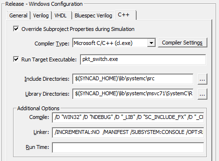
The C++ tab contains the compiler options and compiler used for C++ projects.
•Compiler Type determines the C++ compiler. •Compiler Settings opens the Simulator / Compiler Settings dialog where you can review and edit the compiler paths. |
|
•The Override Subproject Properties during Simulation makes the subprojects use the properties of the top-level project during simulation (and ignore their own private properties). This only affects TestBencher projects that use hierarchical sub-projects. •The Run Target Executable sets the name for the executable program that will be built/run from the C++ source code in the project. •The Include Directories specifies the include directories that will be searched for header files when files are included into a source file. •The Library Directories specifies the directories to search for library files during the build process. •The Compile, Linker, and Run Time options edit box allow you to write additional command line options that will be passed to the tool when it is run. |