6.8 Output Data to a File (VHDL & Verilog) |

|

|
|
6.8 Output Data to a File (VHDL & Verilog) |
|
|
6.8 Output Data to a File (VHDL & Verilog) |
|
|
|
6.8 Output Data to a File (VHDL & Verilog) |
|
|
VHDL and Verilog test benches can write test result data to a file. The output file is a tab-separated format called the SynaptiCAD Test Vector Spreadsheet format. This file can be read by a normal spreadsheet program.
[Vectors] Radix=hex AddrOut DataRead[7:0](bin) A4 10110011 54 11011010 .... |
To output to a file, you first create the output text file that defines the names and sizes of the data and add the file to the File Output folder. TestBencher automatically parses the file and creates the project-level classes and variables needed to write to the file. Inside a timing diagram, you can use a Sample to write the data to the file using the @FileName_out.ColumnName syntax. Each time the timing diagram is applied, the file variables in that diagram will write to the next line of the output file.
1) Create an output file with a header which will be used to make an output class
Create a tab separated text file with two lines using one of the methods described in Section 6.7 SynaptiCAD Test Vector File Format (exporting this file from a timing diagram is generally the best method). These two lines define the names, sizes, and radices of the data to be written out.
[Vectors] Radix=hex AddrOut DataRead[7:0](bin)
|
2) Add the file to the File Output Folder to automatically create the file class and variables:
When a file is added to the project’s Test Vector List - File Output folder, TestBencher will automatically parse the file and create a Class definition with a field for each column of the file. TestBencher also instantiates the class as a file variable in the project. This file variable can be accessed anywhere in the project.
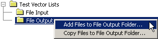
•Under the Test Vector Lists folder, right click on the File Output to open the context menu. |
|
•Choose one of the menu options to attach the file to the project and create the file class and variables. The Add Files to menus will add the file and path to the project. The Copy Files to will make a local copy of the file in the project directory. |
Investigate the class and file variable that were created:
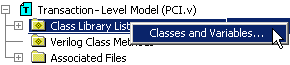
•Right click on the Class Library List folder and choose Classes and Variables to open the Classes and Variables dialog. |
|
•In the Class Definitions tab, notice that a class was created and named filename_STRUCTURE. The fields of the structure are the column headings of the file. |
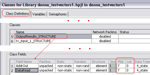
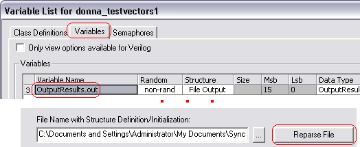
•In the Class Fields section, make sure the field names and sizes match what you want. A blank class field usually indicates an extra space in the test vector file. •If you need to change the output file, double click on the file in the File Output list to open it, make the desired changes, and save it. Next click on the Variables tab, select the file variable, then press the Reparse File button to update the class structure created from the file. |
3) Add Samples to write to the File
A file variable can be accessed using the @FileName_out.ColumnName syntax. One of the easiest ways is to let a sample do the coding for you. For output files, the data captured in the file output variable (one line of data in the file) is written at the end of any transaction that references the file variable.
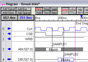
•Put a Sample parameter on the signal or bus whose value is to be written to the output file. •In this example, we used two samples: one for the data bus and one for the address bus. |
|
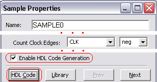
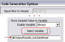
•Double click on the Sample to open the Sample Properties dialog. •Check the Enable HDL Code Generation box. •Press the HDL Code button to open the Code Generation Options dialog. |
|
•Choose an Enable Variable setting like Always, Else, or Then (but not Never). •Press the Select Variable button to select the variable that you want to store the bus value to. |
|
•As a transaction executes, sampled values are stored into the the file variable. Each time the transaction completes, the stored values will be written to the output file. •After simulating the test bench, you can view the output file by double clicking on the file name under the File Output folder in the Project window. |
How to force a line to be written to the output file:
By default, only one line is written to an output file when a transactor finishes executing an Apply call. If you want to write more than one line to the file during a single transactor Apply call (e.g. you want to write multiple values inside a for-loop), add a HDL Code time marker that calls a function like this: For VHDL: WriteToFile(filename_out, filename_out_handle); For Verilog: filename_out.WriteToFile(testbench.filename_out_handle); This will write the current values in the file variable output structure (presumably these values should have been previously set by some samples or other code constructs in the transactor) to the output value. The reason we don't just make a write call after each sample sets a value in the file output variable structure is that it is quite common that the various fields of the structure need to be captured at different times during the transaction. For example, the sample that captures an address value could execute during one clock cycle and the sample that captures the associated data could execute in a subsequent clock cycle after some acknowledgment signal is received. |