6.7 SynaptiCAD Test Vector File Format |

|

|
|
6.7 SynaptiCAD Test Vector File Format |
|
|
6.7 SynaptiCAD Test Vector File Format |
|
|
|
6.7 SynaptiCAD Test Vector File Format |
|
|
The next four sections cover file input and output for the test benches, and each uses the SynaptiCAD Test Vector Spreadsheet format. For either direction, you will first create the data file and then TestBencher will use the information in the header of the file to create the file access class and variables. For output files, only the first two lines of the file need to be created. For input files, you will also need to write in the data values.
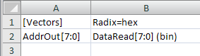
[Vectors] Radix=hex &AddrOut %DataRead[7:0](bin) A4 10110011 54 11011010 .... |
The Test Vector Spreadsheet format is a tab-separated format that can be read or written by a normal spreadsheet program. Test vector files can also be created by defining signal names and sizes in a timing diagram and then saving the diagram in the Test Vector Spreadsheet without timing format.
Rules for the SynaptiCAD Test Vector File Format:
•There can be other lines above the line that contains the [Vectors] statement. Once the [Vectors] is found the rest of the file needs to be in the specified format, until another bracketed section or the end of file is found. •A default radix may be specified for all fields of the file, but if none is specified then a default radix of hex is used. This specification is made with the Radix=type_of_Radix. Each column in a file can individually override the default radix by placing a (radix) after the name and size information. |
[Vectors] Radix=defaultRadix
•The supported radices are: •hex (hexadecimal) •bin (binary) •dec (decimal) •real |
•The line after the [Vectors] line contains the field names and optionally the direction, size and radix of the class field. Put one TAB character between each field name column if you are using an editor to create the file. If you are using a spreadsheet program, export the file in a tab-separated output format. There should be no spaces within the column information. •If no size is given, it is assumed to be a single bit vector. •If no radix is stated, then it is assumed to be the default radix for the file. •If no direction character is used, it is considered an output. The direction characters are @ = input, & = output, and % = in-out. |
(direction)fieldName1[MSB:LSB](Radix)<TAB>fieldName2<TAB>fieldName3
•For input files, the rest of the rows should have data in the columns that match the size and type of the column names. Each data value is separated by a <TAB> character. •See the next four sections for techniques to use the data files. |
Creating a Test Vector file from a Timing Diagram
•The easiest way to make a Test Vector file is to create a timing diagram with the signal names and sizes representing the column headers and export it. Export the diagram using the File > Save Timing Diagram As menu and select the file type: Test Vector Spreadsheet without Timing. |
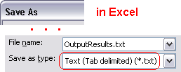
Creating a Test Vector file with Excel
•Another way is to use Excel or a text editor. |
|
•In Excel, we saved as an Other Format of type Text (Tab Delimited). This created a text file were each column is separated by a TAB and there are no spaces within the column information. |
|