8.5 Exporting SPICE Stimulus |

|

|
|
8.5 Exporting SPICE Stimulus |
|
|
8.5 Exporting SPICE Stimulus |
|
|
|
8.5 Exporting SPICE Stimulus |
|
|
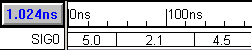
WaveFormer Pro can export waveforms as SPICE voltage sources to provide stimulus for a SPICE netlist. Signals with hexadecimal and binary radixes are converted to real-valued numbers before being exported (the voltage range of the output is set in the Analog Properties sub-dialog of the Signal Properties dialog). Signals with real radixes are exported without conversion. These signals can model simple digital stimulus for digital inputs to a spice model or they can serve as virtual arbitrary waveform generators for driving analog inputs of a model. The ability to generate digital stimulus is particularly handy when using SPICE to analyze the timing and switching characteristics of a digital logic block.
Set the Export and Analog Properties for each signal:
•Select one or more signal names, right-click on a name and choose the Edit Selected Signals menu to open the Signal Properties dialog. Check the Export Signals box. |
|
•If the all the signals have a radix of real then you are ready to export. |
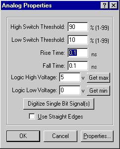
•If the signal radixes are NOT real, then press the Analog Props button to open the Analog Properties dialog. •Set the analog voltage range for the signals using the Logic High Voltage and Logic Low Voltage boxes. •The High Switch Threshold and Low Switch Threshold specifies the high and low detection limit. These percentages determine the point at which the value will be read as the voltage high or voltage low value. •The Rise Time and Fall Time boxes specify the amount of time it takes for the signal to go from the High Switch Threshold to the Low Switch Threshold. |
|
•The Use Straight Edges check box controls whether the SPICE stimulus exports as piecewise linear segments or as stepped voltages. Piecewise linear is more appropriate when modeling pure analog signals, but stepped voltages are more appropriate for modeling the output of a Digital to Analog Converter circuit (DAC). |
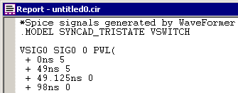
Generated Spice code (Not using straight edges) VSIG0 SIG0 0 PWL( + 0ns 5.0 + 49.0725ns 2.1 + 129.06ns 4.5 + ) Generated Spice code (Using straight edges) VSIG0 SIG0 0 PWL( + 0ns 5.0 + 49ns 5.0 + 49.0725ns 2.1 + 129ns 2.1 + 129.06ns 4.5 + ) |
Export the Signals:
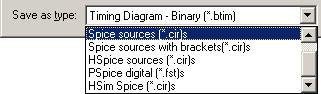
•Select the Import/Export > Export Timing Diagram As menu to open the Save As dialog. •Select a SPICE file type to export from the Save as type drop-down box, enter a file name, and press the Save button to export the file. |
|
•Notice that you can view the generated file in the Report window tab. If you cannot see the Report window, then choose the Window > Report menu option to bring it to the front |
|