5.1 Delays |

|

|
|
5.1 Delays |
|
|
5.1 Delays |
|
|
|
5.1 Delays |
|
|
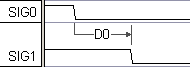
A delay specifies a fixed time or a number of clocking signal edges between two signal transitions. Typically both the min and max values are used in defining delays. If the min and max values are different, the delayed signal transition will be displayed with a gray region of uncertainty. Delays cannot have circular dependencies - if A delays B, and B delays C, then C cannot delay A.
Adding a Delay:
•Press the Delay button so that right clicks will add delays. |
|
•Left click on the first transition in time to select it. |
|
•Right click on the second transition to add the delay. See Section 5.4 on moving delays after they are drawn. |
|
•Double click on the delay to open the Delay Properties dialog, and enter the min or max times (or time formulas like D1.min + 5). See Section 2.5 Time Formulas for Clocks and Parameters for information on the syntax of the formulas. |
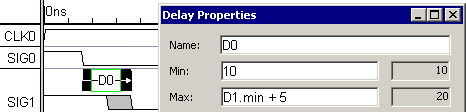
•OPTIONAL: Delays can be clocked instead of time based, by specifying a clocking signal and edge type (pos, neg, or both) in Delay Properties dialog. Once this is done, the min and max boxes will specify the number of edges instead of fixed times. |
|
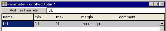
•Notice that the Delay has also been added to the Parameter window. The margin field has no meaning for delays and is marked as "na". |
Delay Add Up:
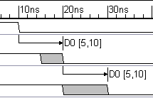
Delays define a timing path through a circuit. As the timing path goes through each gate the delay uncertainty regions will add together. Here both delays have 5ns min and a 10ns max. The first uncertainty region is 5ns wide, and represents the difference between the min and max times of the first delay. The second uncertainty region is 10ns wide. The first edge is set by both delay's min times and the second edge is set by the delay's max times. |
|
Delay Colors and Critical Paths:
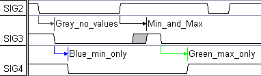
Delays are color coded to indicate which edges of a transition they control. Color coding can be turned off for documentation purposes, by un-checking the View > Show Critical Paths menu.
•Black delays set both the min and max edges of a signal transition. •Blue and green indicate min only and max only edge setting. |
|
•A gray delay sets neither edge of the delayed transition, either because the min/max values are blank, another delay is dominant at the delayed transition, or the delayed edge has been locked. |
Reconciling multiple delays ending on an edge:
If more than one delay ends on the same transition, then the colors will show which delay is responsible for which transition. To resolve this for a particular edge:
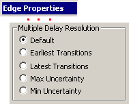
•Double click on the edge to open the Edge Properties dialog and choose a Delay Resolution setting. The default method is set using the Options > General Preferences menu. •Earliest transition: The earliest min edge and the earliest max edge will determine the uncertainty region of the delayed edge. Use this method when a transition occurs after one of several transitions has occurred. |
|
•Latest transition: The latest min edge and the latest max edge will determine the uncertainty region of the delayed edge. Use this method when a transition occurs only when all of a set of transitions have occurred. •Max uncertainty: The earliest min edge and the latest max edge will determine the uncertainty region of the delayed edge (maximizes the uncertainty from forcing edges). •Min uncertainty: The latest min edge and earliest max edge will determine the uncertainty region of the delayed edge (typically not very useful). |
The best way to figure this out is to play with the Multdely.btim timing diagram in the Examples directory.
Common Delay Removal (Reconvergent fanout):
The timing diagram editor automatically accounts for reconvergent fanout effects, correctly calculating margins and distances for parameters. Reconvergent fanout happens when two timing paths share a common transition. The uncertainty of the common transition should not affect distance and margin constraints between transitions further down on the timing paths, because whenever the common transition occurs it occurs at the same time for both timing paths. This effect is called reconvergent fanout because it is only important when a signal fans out to multiple gates and the outputs of these gates reconverge as inputs to a common gate such as a data and a clock signal to a register. If the effects of reconvergent fanout were ignored, a good design might seem to violate a timing parameter because the margin calculations were overly pessimistic. Reconvergent fanout does not change the uncertainties of individual transitions so they are not visible on the timing diagram itself (except for constraint margins and distance values).
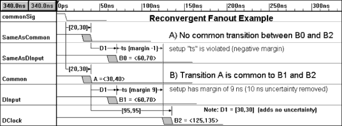
Example: A NAND gate has an uncertainty region of 10ns. Two signal paths fanout from the NAND gate, go through some other gates, and then reconverge at the data(DInput) and clock(DClock) inputs of a D flip-flop. The difference in arrival times of the two paths should just be the delay and uncertainties of the two paths. The 10ns uncertainty of the NAND gate should not affect the difference in arrival times because both signals will start at the same time (somewhere in the uncertainty region of the NAND gate).
Delay Correlation Groups
Even though data sheets for IC's list large min/max uncertainty ranges for each delay, the delays within any particular IC will be much more tightly grouped. To take advantage of this, delays from a particular IC can be added to a correlation group. The editor will then recalculate the setup and hold times so that faster circuits can be designed. Once a delay is added to a correlation group the new calculations are automatically done.
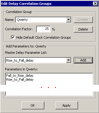
•Double-click on a delay to open the Delay Properties dialog, then click the Correlation button to open the Edit Delay Correlation Groups dialog. •To create a new group, type a group name into the Name box and click the Create button. To access an existing group, just select it from the drop-down Name list. •In the Correlation Factor box, enter the percent correlation for the delays in this group. The percentage must be a whole number between 0 (no correlation) and 100 (fully correlated). •Next, add delays to the group by selecting them in the Master Parameter List and pressing the Add button. |
|
•Notice that the delays are added to the Parameters in group_name list box at the bottom of the dialog. To delete a parameter from this list, just select it and hit the Delete key on the keyboard. •Normally the Hide Default Clock Correlation Groups check box is checked. Clocks automatically create 3 correlation groups to correlate the internal delays specified by the clock buffer delays (specified in Edit Clock Parameters dialog). The auto-generated groups will be named $$Clockname_BufferRising, $$Clockname_BufferFalling, and $$Clockname_BufferRisingFalling, but the user very rarely needs to edit these groups. |