8.1 Analog Waveform Display |

|

|
|
8.1 Analog Waveform Display |
|
|
8.1 Analog Waveform Display |
|
|
|
8.1 Analog Waveform Display |
|
|
To display a signal as an analog waveform, the editor will use the signal's logic high/low voltage to determine the high and low value for the range. Analog signals can be displayed from either a real-valued signal or a multi-bit digital signals (in which case the Analog Display acts like the signal's data being passed to a D/A Converter). If the signal has a radix that is not real (it's a multi-bit digital signal), then the MSB/LSB will be used to determine the resolution of the quantization of the digital value and the high/low voltages in the Analog Properties dialog determine the range of the analog output of the D/A converter.
Display Analog Waveforms:
•Double-click on the signal name to open the Signal Properties dialog, and check the Analog Display box. •To increase the vertical height of the signal, set the Size Ratio box to be greater than 1. |
|
•If radix is NOT real, then make sure to set the MSB and LSB to the proper range for the signal. |
|
•Press the Analog Props button to open the Analog Properties dialog |
|
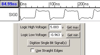
•Set the Logic High Voltage and Logic Low Voltage boxes to specify the minimum and maximum values of an analog signal. •If the radix of the signal is real, the Get Min and Get Max buttons will set the appropriate high/low voltage according to the values found on the signal. |
|
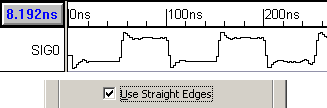
•Normally a slanted line is drawn between the points in an Analog signal. However, if you check the Use Straight Edges setting a vertical line will be used. |
|
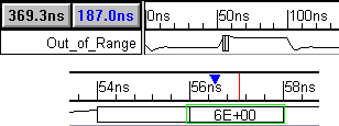
•If a value on the signal is above or below the voltage range, then it will be displayed as a box. If you, zoom in the box will display the value that is out of range. |
|
Converting between Real and Multi-Bit Analog Signals
Sometimes it's useful to convert between real-valued and multi-bit digital signals. Some examples of real-valued signals include data imported from SPICE simulations and signals created using the built-in analog label equations (discussed in the next sections). One example where it can be useful to convert these signals to multi-bit digital signals is if you want to export them to Verilog digital stimulus.
Converting between real and multi-bit signals is done by changing the radix and the MSB and LSB as shown above. Before converting, it is a good idea to look at the Analog Properties dialog to make sure the voltage min, max and range values are what they need to be. These values will control the conversion between the signals.